
-
-
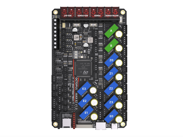
Double check that you have all of the jumpers installed in the positions highlighted in the image and this step here.
-
Powering up with jumpers installed incorrectly can cause irreversible damage to your electronics!
-
Pay special attention to the stepper driver jumpers. These control the voltages going into the driver. Sending 48v to the smaller 24v TMC2209 drivers will cause them to blow.
-
48V Position
-
24V Position
-
For v4.2 these stepper positions are not used as the extruder drivers are on the print heads tool board.
-
-
-
Connect motor cables to the gantry motors as shown.
-
Use the longer twisted cables that are included with the LDO motors.
-
On the rear right corner feed together the static fan, endstop and motor cable.
-
On the front right corner feed the motor cable and camera cable into the base together.
-
The corners on the left side should have just the motor cables going down into them.
-
Tuck the cables into the extrusions and hold in place with the cable tie mounts.
-
Route the cables down into the base.
I went a bit rogue at this point, I saw Step 4 of Stage 06: Wiring and thought "I want to use cable covers", so I printed some out from https://www.thingiverse.com/thing:517751... and used them!
Richard Thomas - Resolved on Release Reply
I wish I had the X endstop mount as shown in the photo, my problem of the gantry all the way to the right not triggering the microswitch might not have happened.
Richard Thomas - Resolved on Release Reply
Also I had to completely undo the camera cable so that I could feed it through the base hole small end first. The USB-A plug won't go through the hole in the base. This should have been mentioned way back when the camera was being installed.
All of the gantry cables should be routed and fed through the holes in the base BEFORE even mentioning the base wiring or the control board. That way all of the cable routing for the top side can be completed before placing the printer on its back side ready for base wiring. It's much easier to do the top side cable routing with the printer right side up than lying down.
The gantry motor cables are twisted. The twisted gantry cables are also much longer than the z motor cables which are flat. I used the wrong cables and had to reroute the cables after discovering the flat ones are TOO short. I see the step after this does mention to use the flat cables for the Z motors.
roger james - Resolved on Release Reply
-
-
-
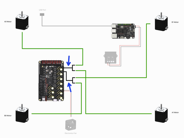
The diagram is orientated relative to the control board and shows the motors in the positions that they would be in if looking up from under the base.
-
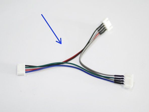
Connect to the control board the two motor cable adapters.
-
Connect to the adapters the four gantry motors as shown in the diagram.
-
-
-
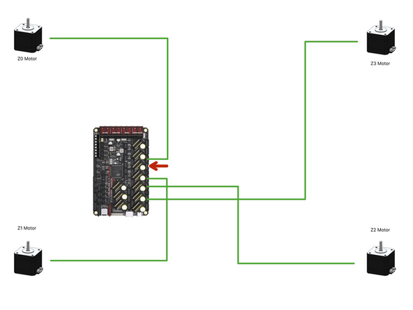
The diagram is orientated relative to the control board and shows the motors in the positions that they would be in if looking up from under the base.
-
Connect the four z-motors to the control board as shown.
-
These are the flat motor cables, not the twisted ones.
-
Note that a connector on the board is skipped out, this is on purpose.
-
-
-
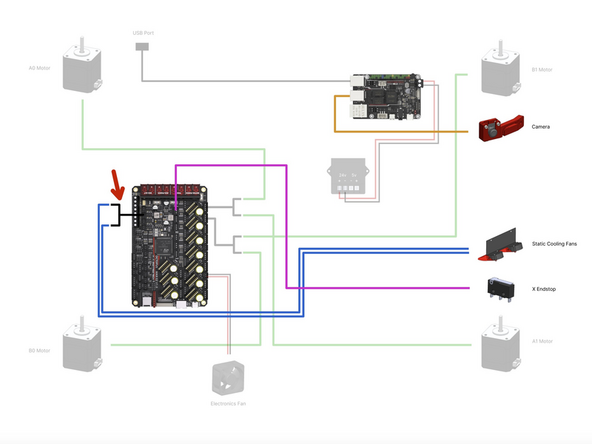
Connect the USB Camera to a free USB port on the BTT Pi board.
-
Connect the X-Endstop to the control board as shown.
-
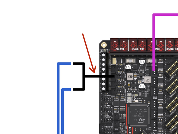
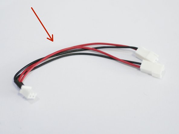
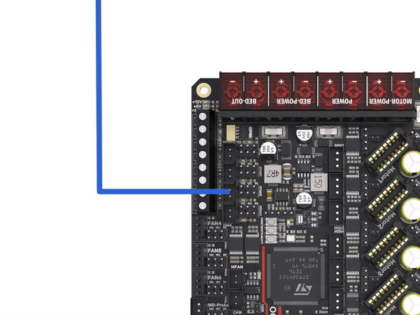
Connect the fan splitter to the control board.
-
Connect to the fan splitter the two static fans.
-
-
-
See the next step if you are building v4.2
-
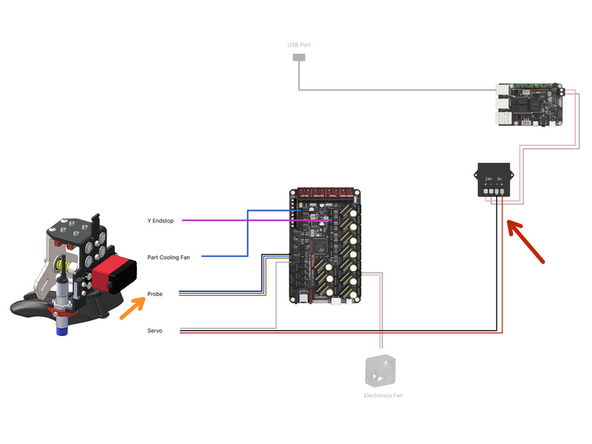
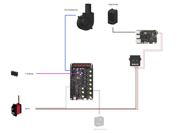
The following cables all come from the tool carriage loom:
-
Connect the Y-Endstop to the control board.
-
Connect the part cooling fan to the control board.
-
Connect the bed probe to the control board.
-
Connect the white servo signal cable to the control board as shown.
-
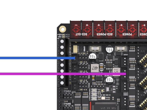
Connect the servos power cables to the 5V output of the convertor. Red to positive and black to negative.
The title to this one should read "Editing Step 7 - Tool Carriage Wiring - Prior to v4.2"
Richard Thomas - Resolved on Release Reply
-
-
-
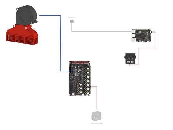
Complete this step if you have the enclosure upgrade installed.
-
Plug the filter fan into the control board as shown.
1 question : normally the filters are supposed to blow out from the enclosure not inside. Is there something i missed?
Xavier GUERIN - Open Reply
My fume fan assembly does not look like this, as there has not been a step to attach the tray bit to the shroud bit.
Richard Thomas - Resolved on Release Reply
-
-
-
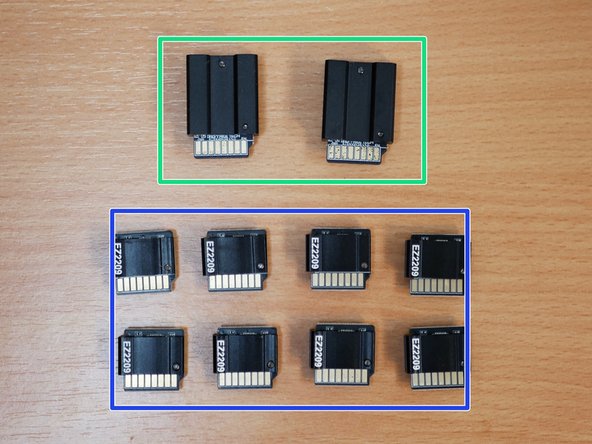
Before unpacking the stepper driver boards make sure that you have grounded yourself. You can do this by touching a large metal object. This is to prevent any static from damaging the drivers when handling them.
-
These drivers can only be plugged in one way. The fin side of the heatsink points to the back of the printer.
-
Plug the TMC5160 RGB EZ Drivers into the board as shown. They will drive the gantry motors.
-
Plug the TMC2209 EZ Drivers into the board as shown. They will drive the Z motors and extruders.
-
If building the 4.2, ignore the E drivers, as these are already on the print head orbiter control boards.
-
-
-
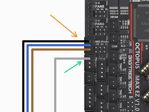
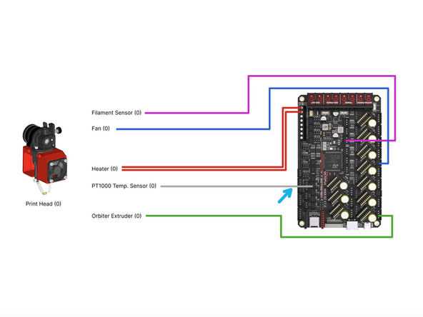
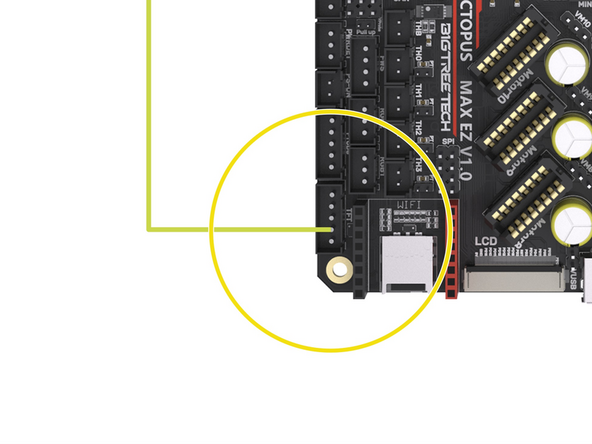
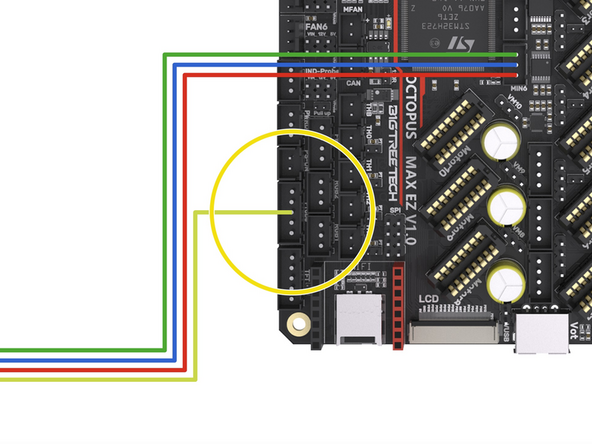
Connect the filament sensor to the control board as shown.
-
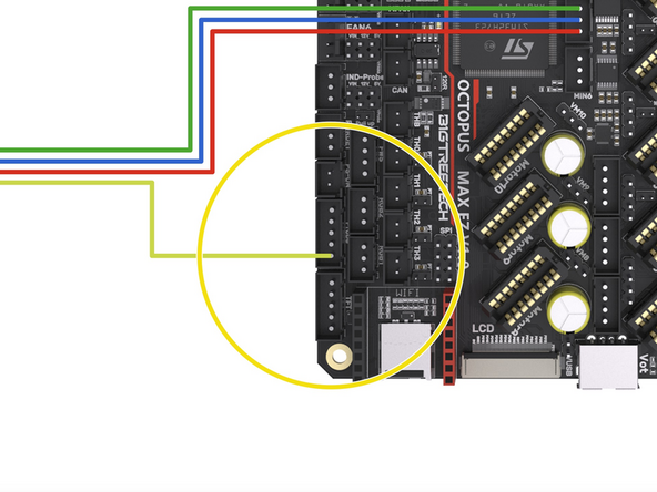
If you are running the Orbiter filament sensor then see the second image for wiring it to the control board.
-
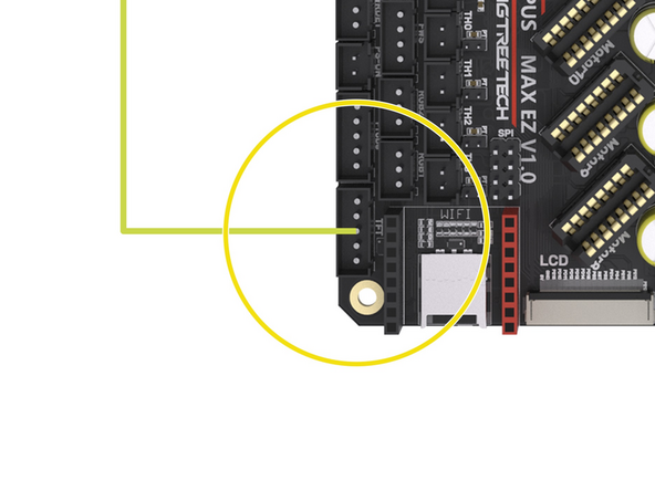
Connect the loose yellow cable from it to the control board as shown. It doesn't have a dedicated position on the control board so we will need to borrow a pin from a header that we are not currently using.
-
We recommend using either tape or a hot glue gun to hold the cable in place.
-
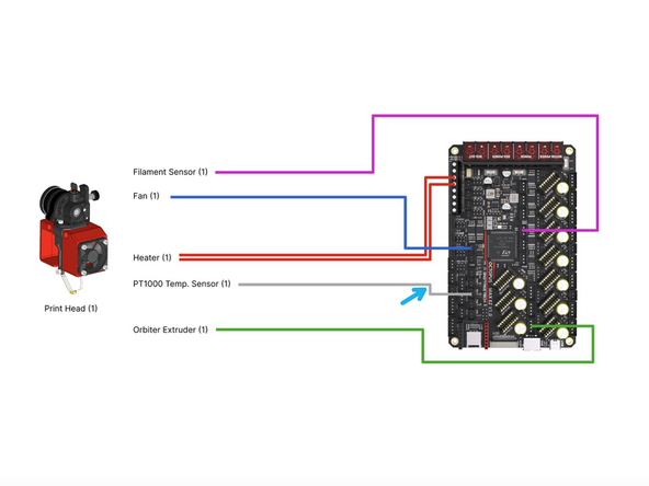
Connect the hotend fan to the position shown on the board.
-
Connect the heater to the HE0 screw terminal on the board.
-
Connect the PT1000 to the TH0 position on the board.
-
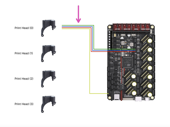
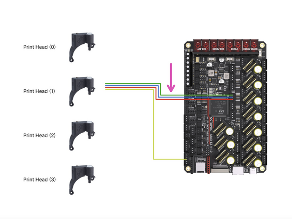
Connect the Extruder to the Motor7 position on the board.
Which one is print head 0? Nearest the front? Nearest the back? Why on earth don't you say? I guess I dig back through the instructions and hope it says somewhere :(
Mark Wheadon - Resolved on Release Reply
Print head 0 is the one nearest the front, thanks for your feedback, we've just updated this step to mention this.
I'm going to assume the front, as that's the first one you say to build. It would be helpful if you said explicitly which is 0 so we can be sure.
I could not get the lone yellow wire to stay connected. It kept falling out. Removed it from the single pin housing and placed it, along with the pin from print head 1 in a 3 pin dupont housing I had laying around. Going with this stop gap measure until proper JST-XH kit arrives in mail. did similar procedure for print heads 2 and 3.
roger james - Resolved on Release Reply
-
-
-
Connect the filament sensor to the control board as shown.
-
If you are running the Orbiter filament sensor then see the second image for wiring it to the control board.
-
Connect the loose yellow cable from it to the control board as shown. It doesn't have a dedicated position on the control board so we will need to borrow a pin from a header that we are not currently using.
-
We recommend using either tape or a hot glue gun to hold the cable in place.
-
Connect the hotend fan to the MFAN position on the board.
-
Connect the heater to the HE1 screw terminal on the board.
-
Connect the PT1000 to the TH1 position on the board.
-
Connect the Extruder to the Motor8 position on the board.
-
-
-
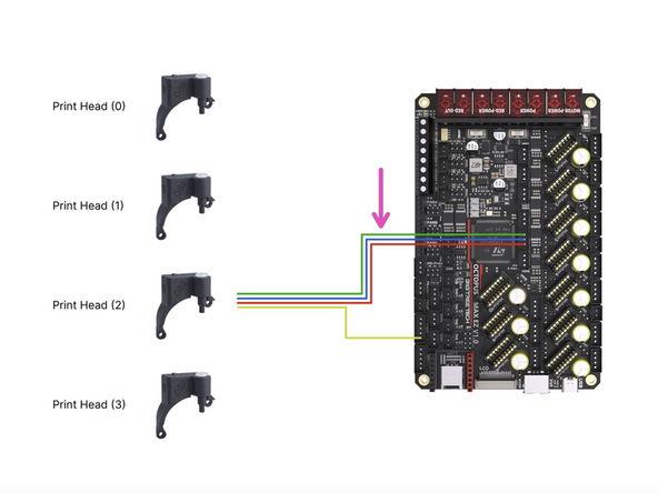
Connect the filament sensor to the control board as shown.
-
If you are running the Orbiter filament sensor then see the second image for wiring it to the control board.
-
Connect the loose yellow cable from it to the control board as shown. It doesn't have a dedicated position on the control board so we will need to borrow a pin from a header that we are not currently using.
-
We recommend using either tape or a hot glue gun to hold the cable in place.
-
Connect the hotend fan to the FAN6 position on the board - this fan is connected to the two lower pins on the header as shown in the diagram, ensure to orientate the black and red cables as shown.
-
Connect the heater to the HE2 screw terminal on the board.
-
Connect the PT1000 to the TH2 position on the board.
-
Connect the Extruder to the Motor9 position on the board.
I'm a little surprised and confused there are no comments about the fan (2) and fan (3) connections. Assuming I have interpreted the illustrations correctly, the molded female 2 pin connectors for these fans connect to a 4 pin connector on the board, using only the lower 2 pins, at their respective fan 5 and 6 locations. Pin separation is compatible but correct + and - orientation the fan connector does force the board pins to "lean" a bit. It's not ideal, it works but it makes me question if I've got it right. Little feedback would be appreciated.
Pete Pubben - Resolved on Release Reply
-
-
-
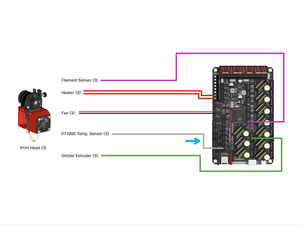
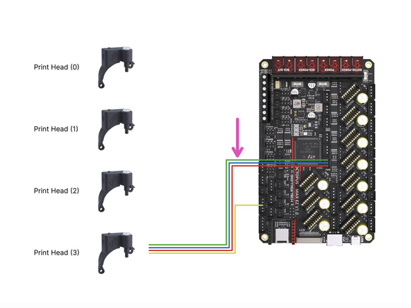
Connect the filament sensor to the control board as shown.
-
If you are running the Orbiter filament sensor then see the second image for wiring it to the control board.
-
Connect the loose yellow cable from it to the control board as shown. It doesn't have a dedicated position on the control board so we will need to borrow a pin from a header that we are not currently using.
-
We recommend using either tape or a hot glue gun to hold the cable in place.
-
Connect the hotend fan to the FAN5 position on the board - this fan is connected to the two lower pins on the header as shown in the diagram, ensure to orientate the black and red cables as shown.
-
Connect the heater to the HE3 screw terminal on the board.
-
Connect the PT1000 to the TH3 position on the board.
-
Connect the Extruder to the Motor10 position on the board.
-


Cancel: I did not complete this guide.
13 other people completed this guide.

I would install the stepper drivers now, as described in step 12. before board is covered in wires.
alex netzer - Resolved on Release Reply