
-
-
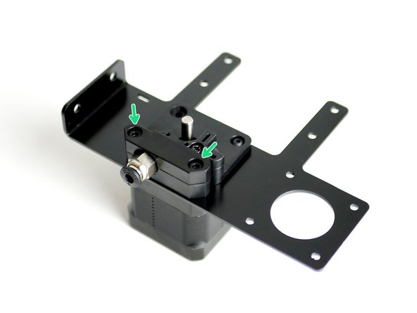
Place the Extruder Mounting Bracket onto a motor. The motors pin connector should be pointing to the back of the bracket like shown.
-
Secure the extruder back plate with a single M3 x 8mm bolt through the top right hole.
-
-
-
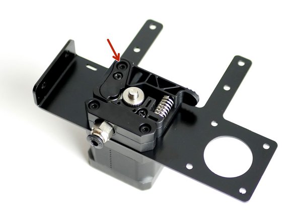
Fix the Coupling Bracket onto the motor with two M3 x 18mm cap head bolts.
-
-
-
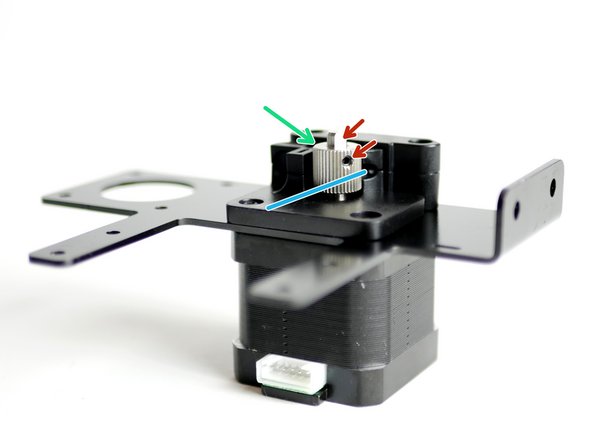
Align the drive gear so that it runs with the filaments path.
-
Filament path
-
Fix the Drive Gear to the shaft of the motor.
-
Tighten the set screw onto the flat of the shaft. Tighten firmly.
-
-
-
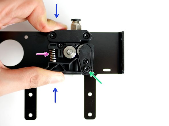
Place in position the Extruder Spring on the Back Plate.
-
Drop in a M3 x 18mm cap head bolt
-
Compress the spring with the Idler Arm as shown in the first image.
-
Tighten down the M3 x 18mm bolt
-
Do not over tighten, the arm should still be able to pivot.
-
-
-
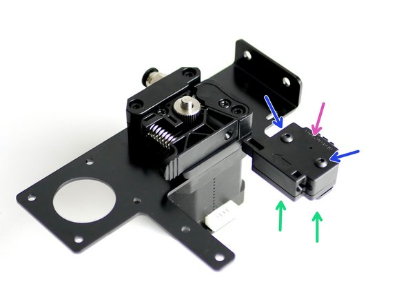
Fix the filament sensor to the Extruder Mounting Bracket:
-
Filament Sensor
-
Two M3 x 20mm bolts
-
Two M3 Nyloc Nuts
-
Match the orientation of the Filament Sensor as shown in the photo.
-
-
-
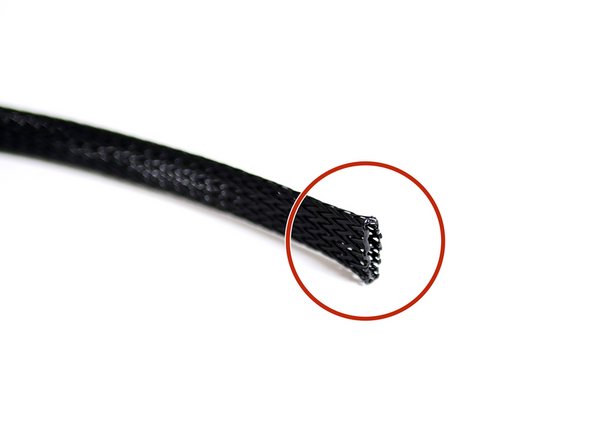
Cut 60CM of Braided Cable sleeving
-
Melt the ends with a lighter to prevent them from fraying out.
-
-
-
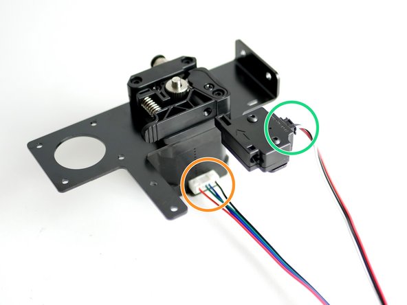
Connect the filament sensor cable to the filament sensor.
-
Connect a motor cable to the motor.
-
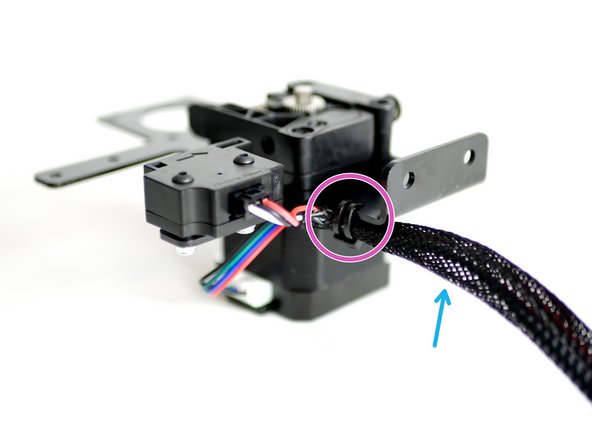
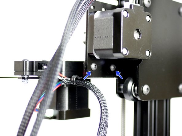
Feed onto both of the cables the braided cable sleeving.
-
Cable tie the cables to the mounting bracket.
-
-
-
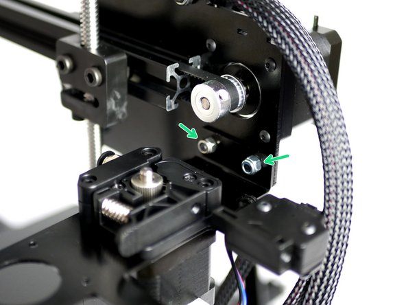
Fix the Extruder Assembly onto the Z-Carriage
-
M4 x 10mm bolt
-
M4 Nyloc Nut
-
-
-
If you are building the Proforge 2/2S with the Dual Switching Extruder stop here and continue the build guide from the Dual Switching Extruder guides here.
-
-
-
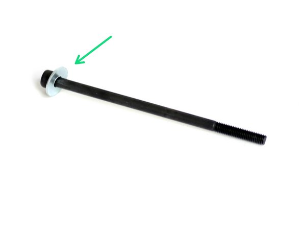
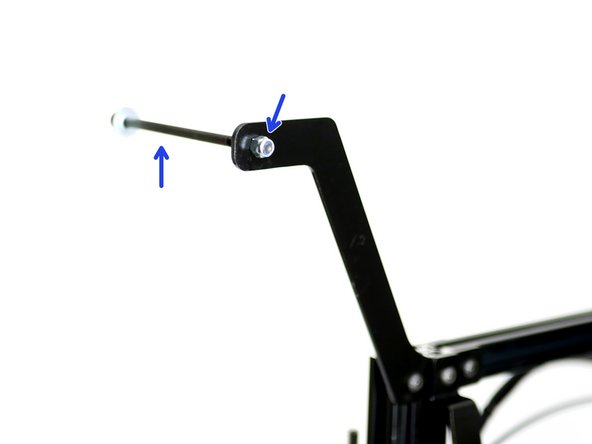
Slide onto a M5 x 100mm bolt an M5 15mm washer.
-
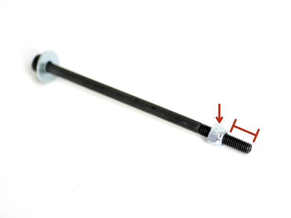
Fix to the bolt an M5 Nyloc Nut about 1cm of the way up.
-
Fix the bolt to the top of the Extruder Mount with another M5 Nyloc nut.
-
-
-
If you do not intend on installing the Dual Switching Extruder you can cut the tubing down to 50CM before installing.
-
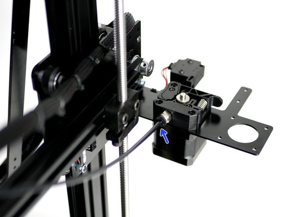
Insert one end into the PTFE Tubing into coupling on the Extruder.
-
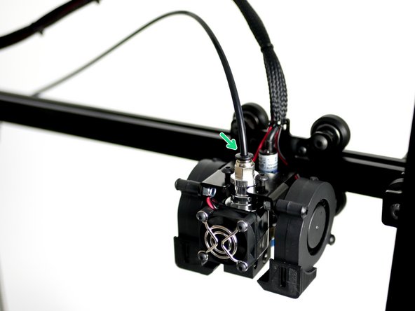
Insert the other end of the PTFE Tubing into the Hotend, make sure that it is fully inserted up to the nozzle.
-


Cancel: I did not complete this guide.
20 other people completed this guide.
