
-
-
The Proforge 300 is powered by Klipper Firmware which is an open source 3D printer firmware developed by the very talented Kevin O'Connor.
-
The BTT Pi v2 board is an SoC (System On a Chip) board - essentially a mini-computer. It is what runs Klipper and can be considered the "brain" of the 3D printer.
-
The SKR 3 EZ board is a controller board. It takes instruction from the Pi board and controls the various components on the printer. It can be considered as the "nervous system" of the printer.
-
The SO3 Tool Board is a controller board similar to the SKR board but designed for the print head.
-
The Eddy Probe also needs firmware flashing to it.
-
Each board has its own firmware. In this stage we will flash these four firmware's - starting with the Pi board.
-
-
-
Download the Klipper Firmware Image here.
-
Last updated 02/05/2025
-
Extract the .zip file after downloading. On Mac you can double click to do this, on Windows you can use WinZip.
-
-
-
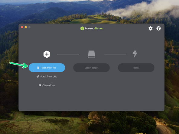
To Flash the SD card you will need an image writing tool. We recommend using Balena Etcher.
-
To edit text files you will need a text editor, we recommend:
-
Windows: Notepad++
-
Mac: Sublime Text
-
-
-
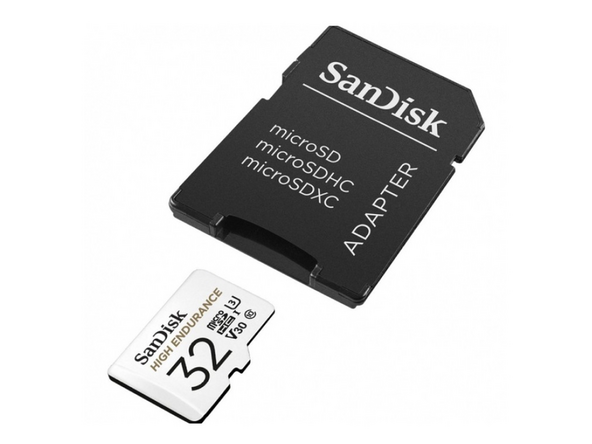
Take the included 32GB SanDisk SD card and flash onto it the Klipper firmware image that you downloaded in the previous step.
-
Ensure that before flashing the firmware you have extracted the .IMG file
-
Use Balena Etcher to do this.
-
The process will take roughly 10min.
-
After flashing it, keep the SD card plugged in for the next step.
-
-
-
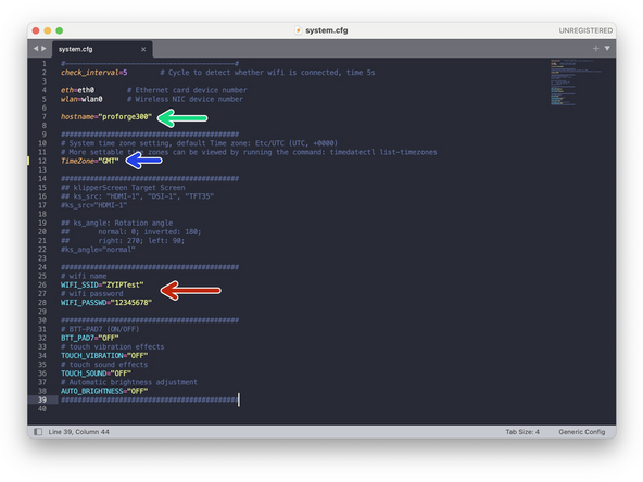
The Flashed SD card should now show up named BOOT, go to it and open the system.cfg file.
-
MAC's can sometimes struggle to open this type of storage format - we're working on a way around this so currently you will need to use a Windows device to access this file.
-
Name your printer, default is ProForge 300
-
Set your timezone. Use the list here.
-
Input your WiFi networks name and password.
-
Make sure that you keep the " " quotation marks.
-
Save the file when done.
-
-
-
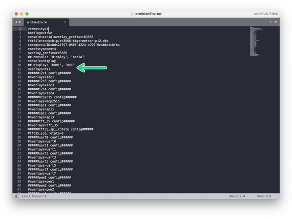
Open the armbianEnv.txt file to check the touch screen display is enabled via dsi.
-
overlays=dsi
-
-
-
Carefully lay the printer down on its back. Let the base of the printer hang off the tables edge to allow access for the power cable.
-
The printer should stay on its back like this until we have completed the firmware flashing stage.
-
Insert the flashed SD card into the BTT Pi board as shown.
-
-
-
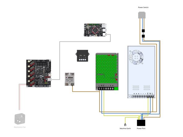
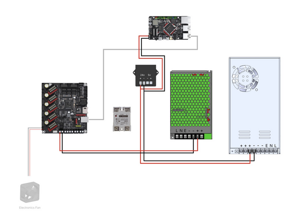
Check your wiring, in particular the mains wiring from the power port to the two power supplies and the wiring from the power supplies to the control boards.
-
Check that none of the cables are loose from their terminals.
-
Check the power supplies have their voltage input switches set to your mains voltage, 230V for Europe and 110V for North America.
-
When happy plug the cable into the back of the printer and flip the switch at the front to power up.
-
Be careful when powering up, the electronics will be exposed in this stage - do not touch terminals when powered up!
-
-
-
On first boot the printer may cycle through boot ups. If you have the touch screen installed, you will notice this on the screen.
-
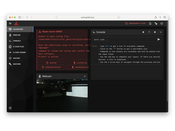
When the printer has successfully connected to your network you will also be able to access it through a web browser that's on the same network.
-
You can do this by going to proforge300.local
-
If the .local address is not working, check your router for connected devices to find the IP address of the printer. Use that IP address in place of the proforge300.local.
-
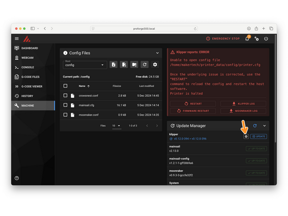
It is normal to see an error here that the printer cannot connect, this is because we still need to flash firmware to the other boards.
-
Check that the electronics fan on the base is spinning.
-
-
-
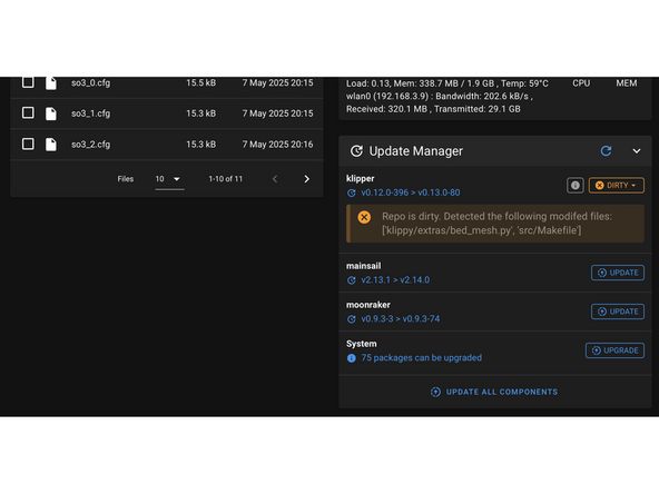
Do not update components of the firmware - doing so may break certain aspects of the configuration.
-
This is normal.
-
-
-
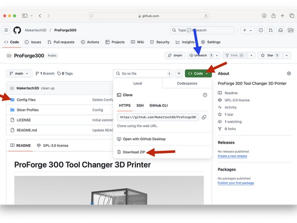
Download the ProForge 300 config files here.
-
Updates:
-
We advise creating a GitHub account and following our repository to get notified every time there is an update to a config file or slicer profile. This will ensure that your printer is always up to date and operating at its best!
-
-
-
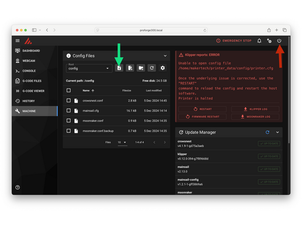
Upload all of the downloaded config files to your printer.
-
Once uploaded restart klipper by pressing the power button in the top right.
-
-
-
Firmware for the various control boards is created using Klipper on the Pi.
-
In order to access the Pi we will use a software called Termius. Download it here.
-
The free version of the software is enough for what we need to do.
-
-
-
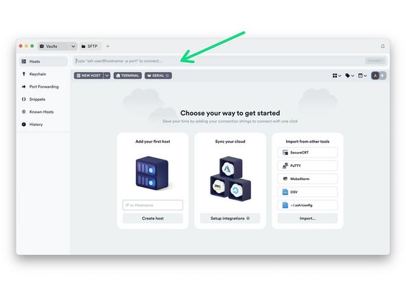
Install Termius and run through the set up wizard until you reach this dashboard.
-
In the text bar at the top type in the following:
-
ssh makertech@proforge300.local
-
The username and password is makertech
-
If you changed the printers name from the default ProForge 300, use that name after the @.
-
Make sure the printer is powered up and the Pi is connected to your local network.
-
If you are having issues with WiFi check either the touch screen or your router settings to see whether printer is connected. You can also connect to the Pi via ethernet for a more stable connection.
-
-
-
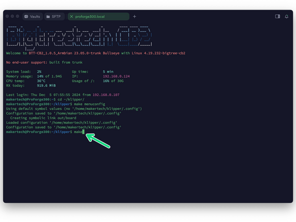
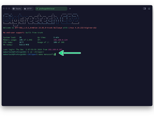
After logging in send the following commands to the terminal:
-
cd ~/klipper/
-
followed by:
-
make menuconfig
-
-
-
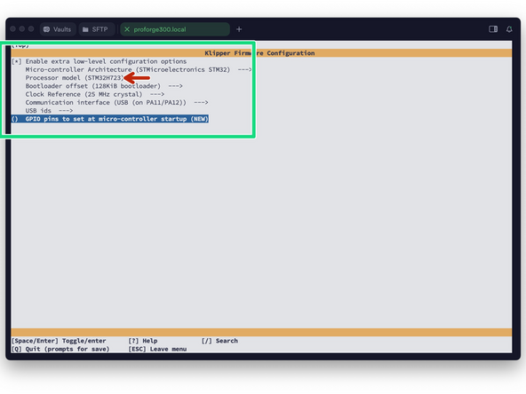
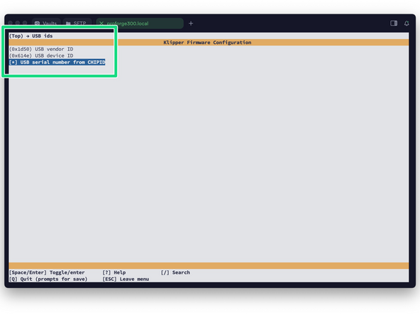
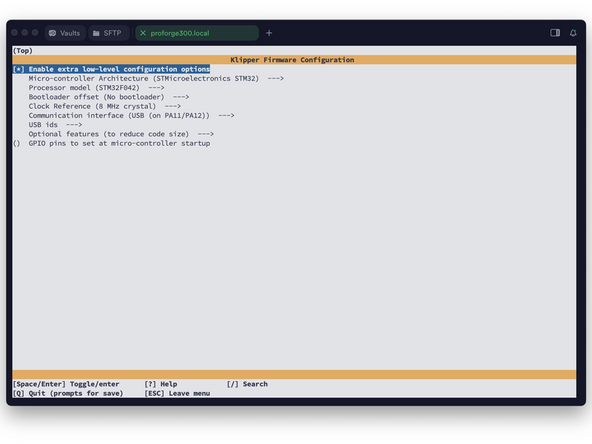
You should now see a config menu, use the arrow keys on your keyboard to match the options selected in the image.
-
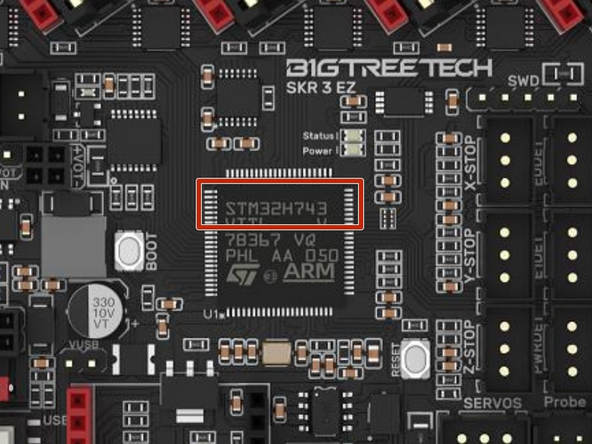
Double check your control board - some use the STM32H743 chip. The chip model is marked on the chip itself.
-
When done, press Q and then Y to save.
-
-
-
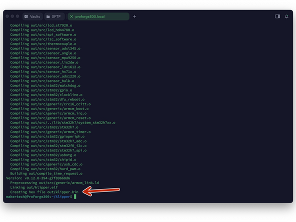
Send a make command to create the firmware file.
-
At the end of the process, you should have a klipper.bin file as shown.
-
-
-
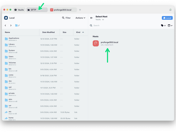
Go to the SFTP tab and press Select Host to open up the file browser for the Pi.
-
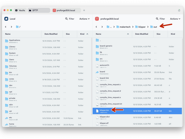
Navigate to the klipper.bin file by going to:
-
home -> makertech -> klipper -> out
-
Drag and drop the klipper.bin file to a folder on your computer.
-
-
-
Rename the klipper.bin file to firmware.bin
-
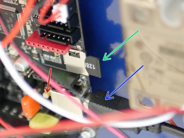
Take the 128mb micro SD card and copy onto it the firmware.bin file.
-
With the printer powered off:
-
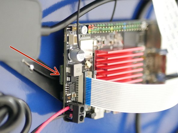
Insert the SD card into the SKR Board.
-
Ensure this white switch is in the "popped-up" state.
-
Ensure the USB cable is plugged in.
-
Power back on the printer to flash the board.
-
-
-
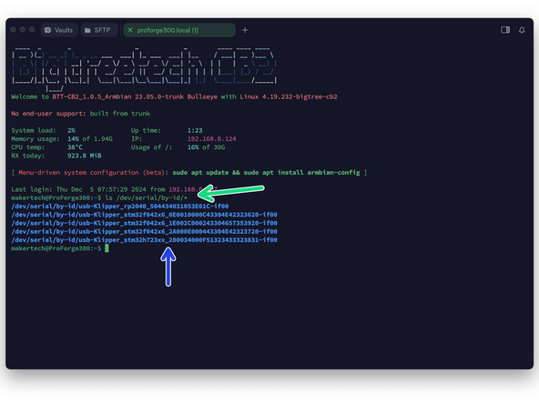
Use Termius to SSH back into the printer in order to retrieve the boards serial id.
-
Ensure that the SKR board is connected to the Pi via USB.
-
Find your unique id by sending:
-
ls /dev/serial/by-id/*
-
The serial id for the SKR board should have stm32h723 or stm32h743 in its name - the other id's are for the eddy probe and print heads.
-
It should be written in the format shown. If you see the word MARLIN or FS_MODE in the id then the board has not flashed correctly - repeat the previous steps. You can also plug the board directly into your pc to copy the firmware.bin file across, bypassing the SD card if it is causing issues.
-
Also note that when flashed successfully the firmware.bin file on the SD card should have renamed itself to firmware.cur.
-
-
-
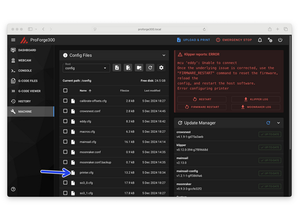
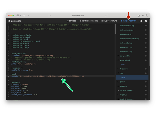
In mainsail open the printer.cfg file that you previously uploaded.
-
Paste the line that you previously copied here.
-
Ensure to match the format as shown in the image.
-
Click Save & Restart when done.
-
-
-
The firmware for the Eddy is created in much the same way as the firmware for the mainboard.
-
Connect to the printer using Termius and enter:
-
cd ~/klipper/
-
Followed by:
-
make menuconfig
-
-
-
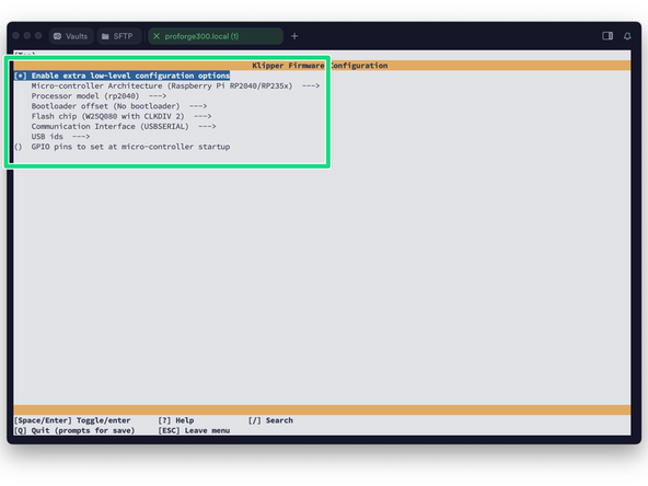
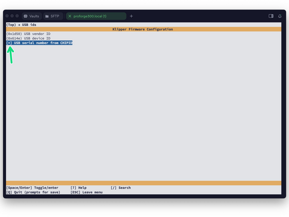
After opening the config menu, use the arrow keys on your keyboard to match the options selected in the image.
-
When done, press Q and then Y to save.
-
-
-
Before being able to flash the Eddy probe we need to put it in Boot Mode - this can be a little tricky and you may need a hand to help you with it.
-
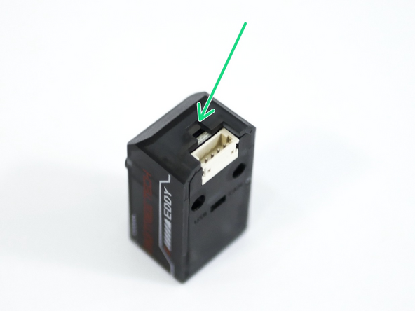
Put Eddy into Boot Mode by:
-
With the printer powered up disconnect the Eddy USB cable and reconnect it whilst holding down the boot button.
-
You should be able to reach the button with a small Allen key or bent paper clip.
-
-
-
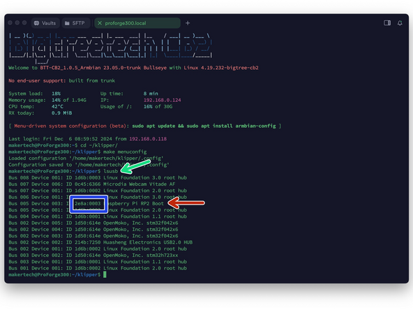
In Termius send the following command:
-
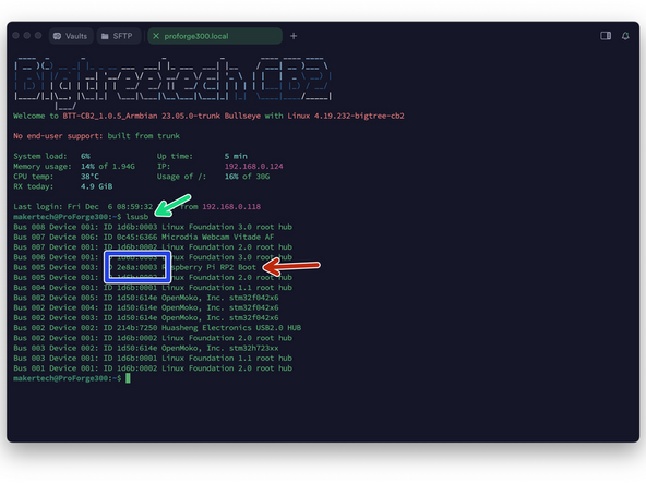
lsusb
-
It should return with the Eddy in Boot Mode.
-
Note the device ID, in our case 2e8a:0003
-
-
-
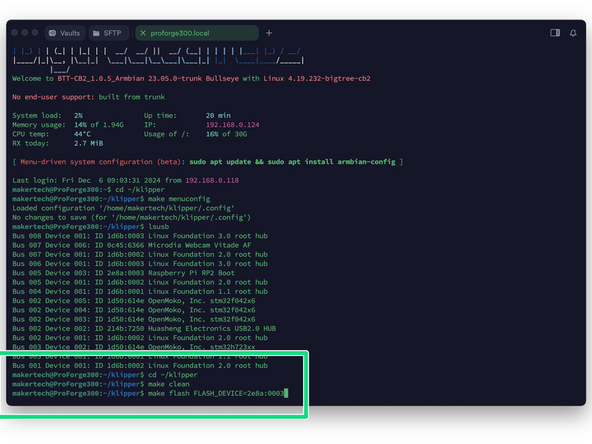
Send the following command:
-
cd ~/klipper
-
Followed by:
-
make clean
-
make flash FLASH_DEVICE=2e8a:0003
-
Where 2e8a:0003 is your device ID from the previous step.
-
Makertech password is makertech
-
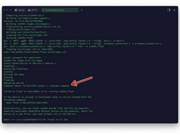
It should take a minute to flash. You may get a failed to reboot error - ignore this. Manually reboot Eddy by unplugging and plugging it back into the Pi.
-
-
-
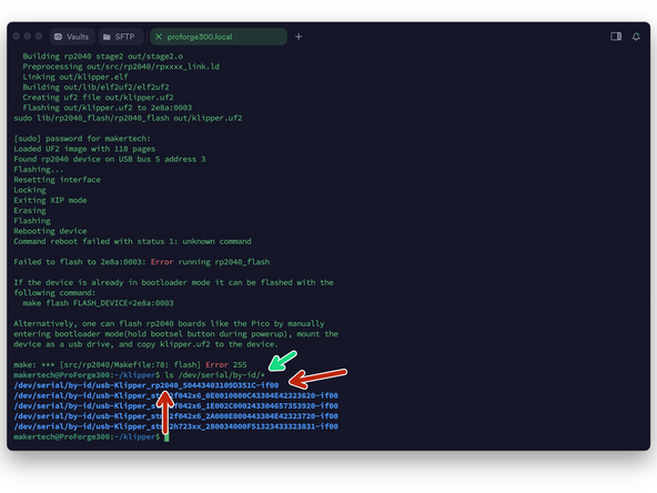
Send the following to find Eddy's Serial ID:
-
ls /dev/serial/by-id/*
-
Copy the Eddy's Serial ID to your clipboard - this will be unique for you. It will be the one with rp2040 in its name.
-
-
-
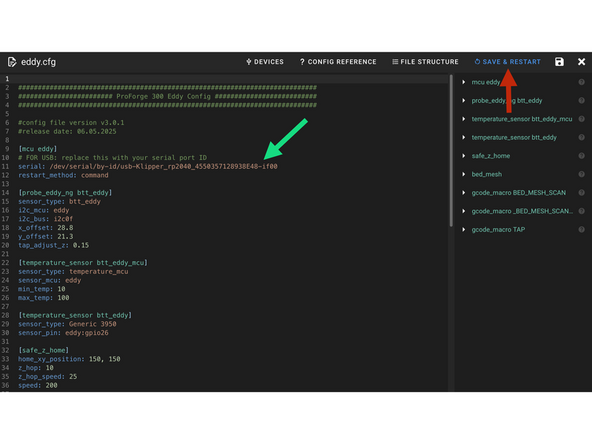
Insert the Serial ID into the Eddy.cfg file.
-
Make sure it is in the same format as shown.
-
Save and restart when done.
-
-
-
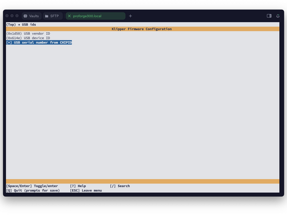
The firmware file for the Print Head Tool Board is created in the same way as the previous boards.
-
In Termius enter:
-
cd ~/klipper/
-
Followed by:
-
make menuconfig
-
Learn more about the Orbiter Tool Board here.
-
-
-
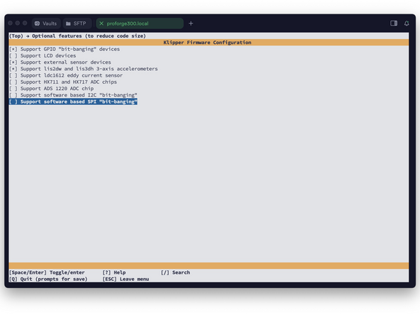
After opening the config menu, use the arrow keys on your keyboard to match the options selected in the image.
-
When done, press Q and then Y to save.
-
Before exiting, thoroughly double check that the settings match as shown here, incorrect settings will cause errors.
-
-
-
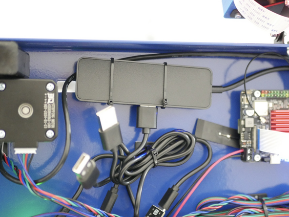
Connect via USB just the print head tool board you are flashing - starting with print head 0, the one nearest the front of the printer.
-
We recommend connecting and disconnecting print heads from the USB hub and not the print head as at the print head there will be a live 24v line.
-
-
-
Take care when handling a print head - the fan will be spinning.
-
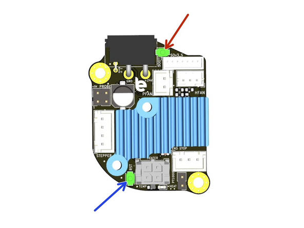
In order to flash a tool board we need to put it in DFU mode. With the printer powered up and the tool head connected hold the following buttons in this order:
-
Boot
-
Reset
-
Then release the reset button.
-
Followed by the boot button - the board will now be in DFU mode.
-
The buttons might be a little tricky to access. Use a ceramic screwdriver or simple toothpicks to push the buttons and avoid creating any short over the board with metal tools
-
When in DFU mode the white hotend LED near the nozzle should shine.
-
-
-
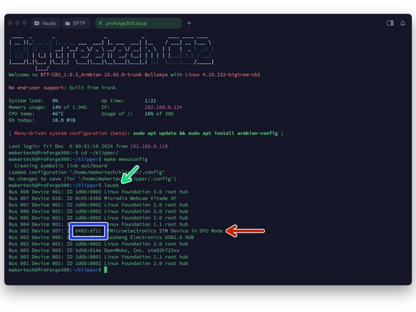
Verify DFU mode by sending this command again:
-
lsusb
-
You should see the board in DFU mode.
-
If the board is not showing in DFU mode unplug and replug the USB Hub from the Pi. Wait a moment and check again by re-sending the lsusb command.
-
Note the ID, in our case 0483:df11
-
-
-
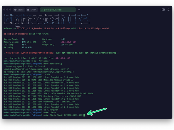
Send the following command:
-
cd ~/klipper
-
Followed by:
-
make clean
-
make flash FLASH_DEVICE=0483:df11
-
Where 0483:df11 is your device ID from the previous step.
-
Makertech password is makertech
-
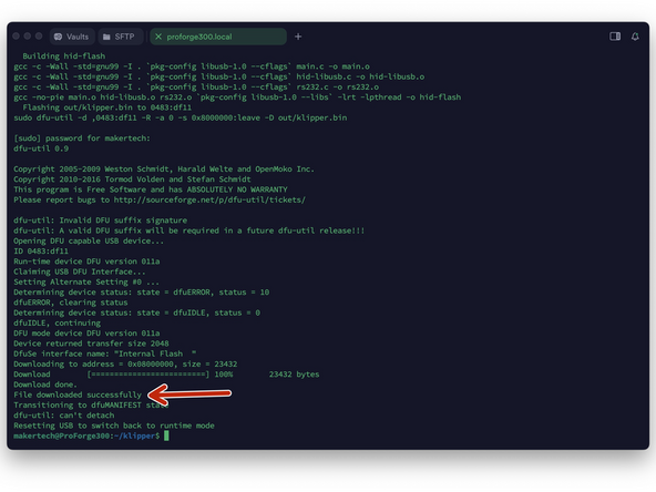
It should take a minute to flash. You may get an error - ignore this. As long as you have a File downloaded successfully response the board has been flashed
-
-
-
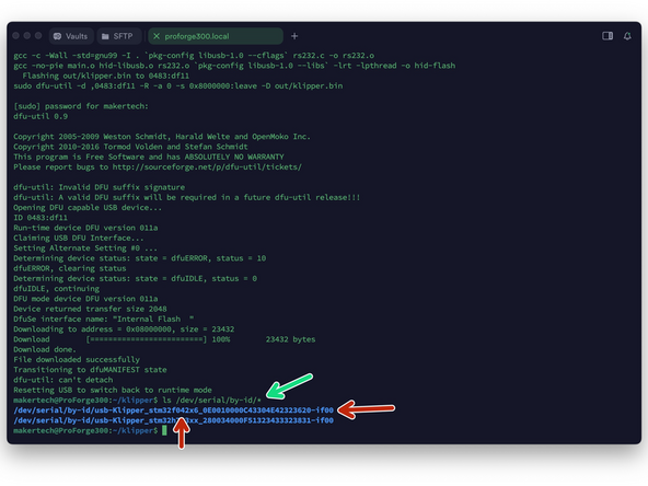
Send the following to find Print Head's Serial ID:
-
ls /dev/serial/by-id/*
-
Copy the Tool Boards Serial ID to your clipboard - this will be unique for you. It will be the one with f042 in its name.
-
-
-
Insert the Serial ID into the corresponding so3_x.cfg file.
-
Where x is 0 for the first print head
-
Make sure it is in the same format as shown.
-
Save and restart when done.
-
-
-
Follow from step 30 again and flash the other print heads in the same way.
-
Each print head will have its own unique serial ID which needs to be entered into its own unique .cfg file.
-
Remember to only plug in the print head you are flashing into the USB hub because each tool board will have unique serial id and this will make identifying print heads easier.
-
-
-
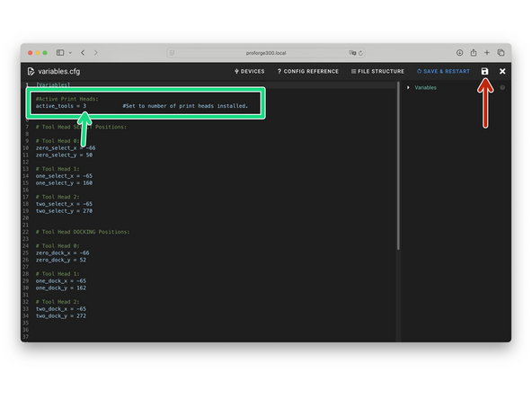
In the Variables.cfg file set the number of active print heads.
-
If you have just one print head installed set the value to 1, and so on...
-
Print heads should be installed in order from the front of the printer. If you are installing two print heads, install them in the first and second positions.
-
Save when done.
-
-
-
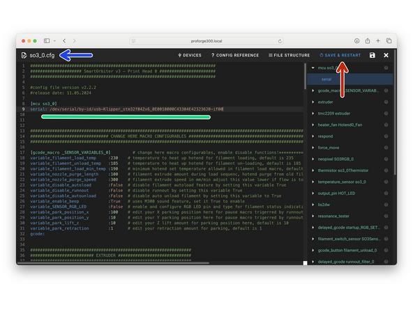
Activate the print heads you have installed by removing the # at the front of the [include so3_x.cfg] line in the printer.cfg file.
-
Make sure to remove the # from in front of each print head you have installed or else it will not be activated.
-
Save and restart when done.
-
-
-
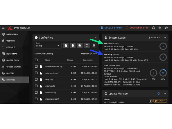
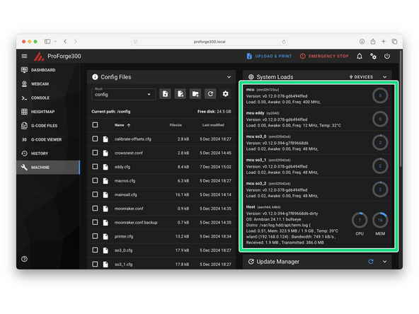
After restarting and given you have your board, Eddy Probe and Print Heads flashed correctly they should all be connecting to Klipper as shown.
-
If you're getting an error you may need to re-flash the indicated component or double check the serial id has been entered correctly.
-
If you're still stuck you can get support via the Facebook Group, Discord Server or emailing us at info@makertech3d.com
-
For klipper related issues google can also be a good resource as klipper is an open-source firmware with a large user base.
-
-
-
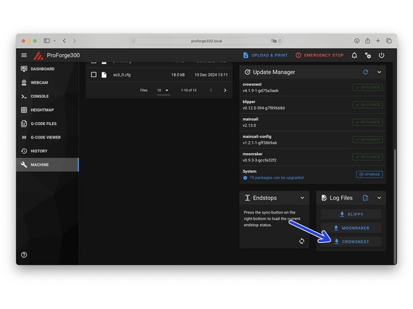
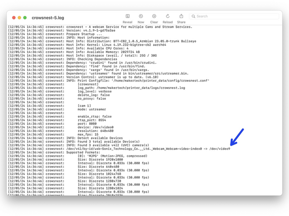
Check the cameras device ID in the Crowsnest log file.
-
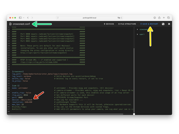
Open the Crowsnest.cfg file.
-
Set device ID to what you found in the Log file: /dev/video9
-
Save and restart when done.
-
-
-
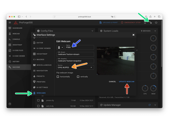
Go to setting and add a webcam.
-
Name it P300 or anything else you would like.
-
Set the streamer service to UV4L-MJPEG
-
Save when done.
-
If the camera feed drops out intermittently, follow these steps:
-
Try the Adaptive MJPEG-Streamer (experimental) service
-
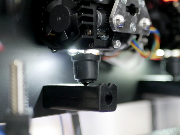
Ensure the connector is securely mounted and the cable is free of kinks, especially in exposed areas.
-
The cable is shielded, but interference can still occur. Route it away from other cables, especially motor cables, minimising crossings. Ensure you have it routed down the other side of the extrusion to the motor cable.
-
-
-
Ready to move onto the next stage? Click here.
-


![Activate the print heads you have installed by removing the # at the front of the [include so3_x.cfg] line in the printer.cfg file.](https://d3t0tbmlie281e.cloudfront.net/igi/makertech-3d/AQkQegRLcSCr24yu.medium)
Cancel: I did not complete this guide.
2 other people completed this guide.
