
-
-
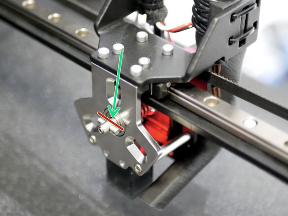
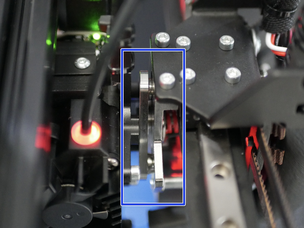
Adjust the servo arm so that at its lowest value the shafts side face is parallel with the servo body.
-
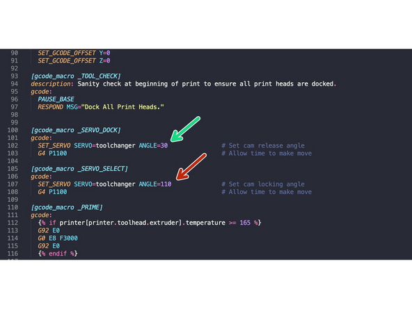
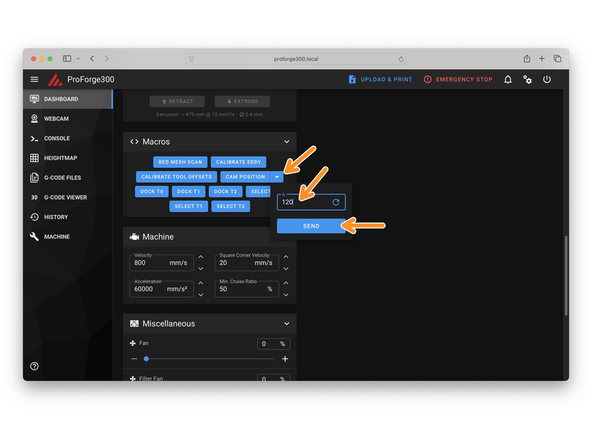
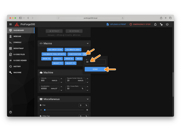
Adjust the value here - we found 30 to work well.
-
Make a note of this number - this will be your docking angle
-
-
-
Before reinstalling the servo spring mechanism add grease to the spring and the servo's cam shaft.
-
We recommend a using high pressure/lithium grease. It should be easy to source locally.
-
-
-
Re-install the servo with the locking mechanism.
-
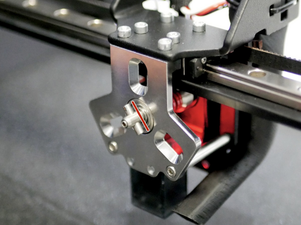
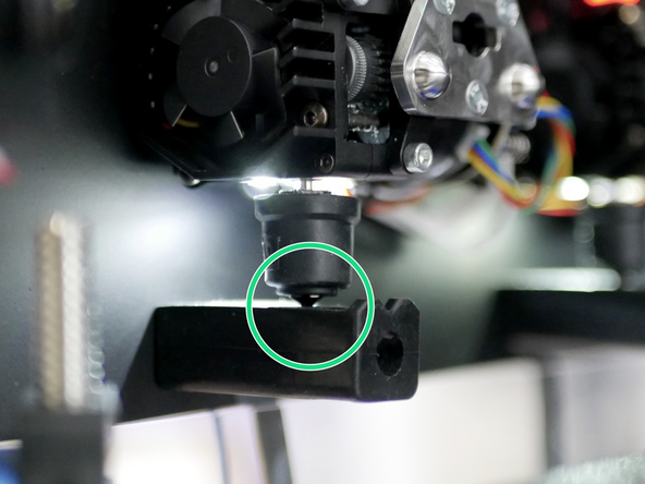
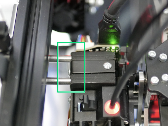
Attach the cam shaft to the servo shaft so that the cam pin is horizontal when the servo is at its docking angle.
-
Add grease to the inside of the cam pin also.
-
-
-
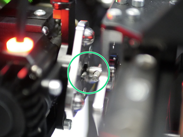
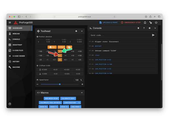
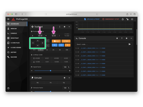
Next we need to set a select angle value - we found 110 works well.
-
After sending the command the cam pin should rotate anti-clockwise to a position just left of vertical.
-
-
-
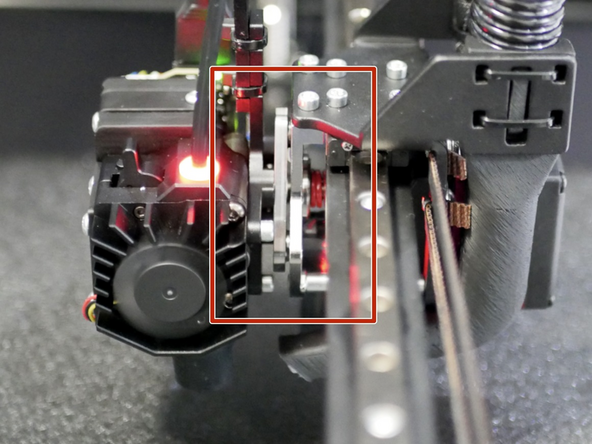
Restore the cam pin to its select angle (30/horizontal).
-
Manually move the tool carriage over to a print head and insert the cam pin into the tool plate.
-
Send the servo select command (110)
-
The carriage should pick up the print head.
-
Check that it is secure.
-
Release when happy and re-dock.
-
-
-
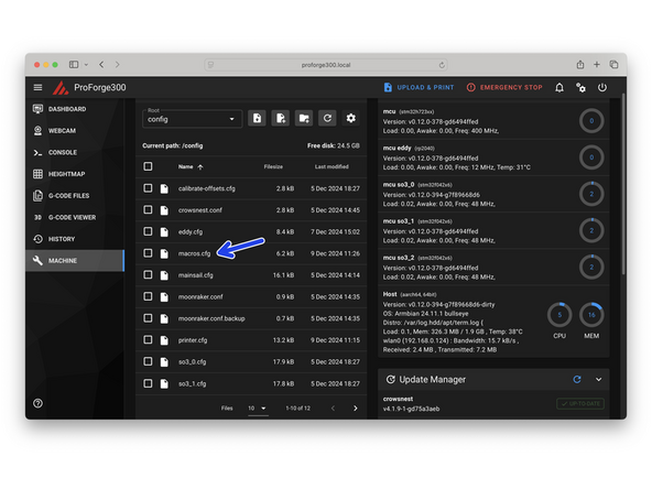
In the macros.cfg file enter in your Dock and Select angles.
-
Dock Angle
-
Select Angle
-
Save and Restart when done for the changes to take effect.
-
-
-
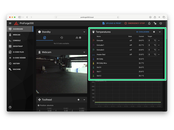
In the mainsail dashboard check that you are receiving the correct temperature readings for all installed components - i.e. room temperature
-
Eddy temp may be higher - this is ok.
-
-
-
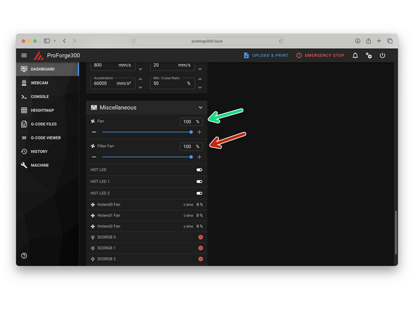
Set the part cooling fan to 100%
-
Set the filter fan (if installed) to 100%
-
Check that all of the fans are spinning.
-
-
-
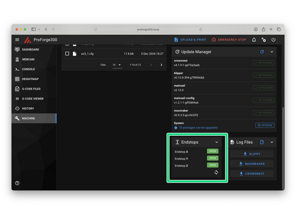
With the print head moved to the middle of the build space, so as not to trigger any of the endstops, check their status.
-
They should report as open.
-
-
-
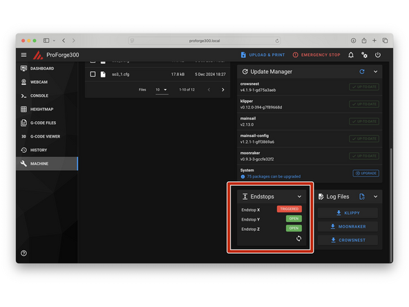
Move the gantry all the way to the right so as to trigger the X-Endstop.
-
Refresh the endstop status window - the X-Endstop should report back as triggered.
-
-
-
Move the Print head all the way to the back so as to trigger the Y-Endstop.
-
Refresh the endstop status window - the Y-Endstop should now report back as triggered.
-
-
-
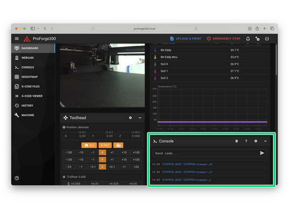
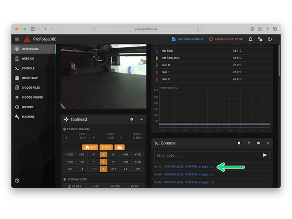
After sending the below commands the corresponding motor should turn anti-clockwise by a small amount and then return to its original positions.
-
Send the command: STEPPER_BUZZ STEPPER=stepper_z to test the front left motor.
-
Send the command: STEPPER_BUZZ STEPPER=stepper_z1 to test the rear motor.
-
Send the command: STEPPER_BUZZ STEPPER=stepper_z2 to test the front right motor.
-
-
-
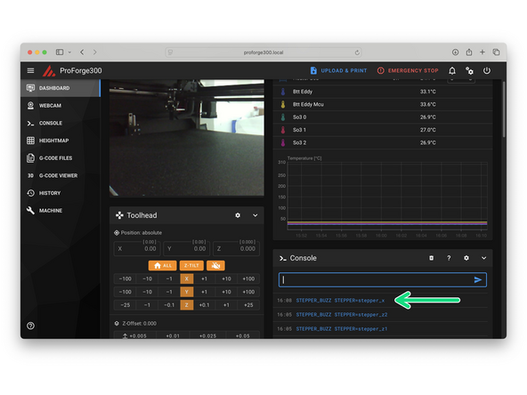
In our Quad-Core-X-Y motion system the "X motors" are the front left and rear right gantry motors.
-
Send the command: STEPPER_BUZZ STEPPER=stepper_x
-
The front left and rear right motors should turn clockwise by a small amount and then return to their original positions.
-
-
-
In our Quad-Core-X-Y motion system the "Y motors" are the rear left and front right gantry motors.
-
Send the command: STEPPER_BUZZ STEPPER=stepper_y
-
The rear left and front right motors should turn anti-clockwise by a small amount and then return to their original positions.
-
-
-
Keep your finger on the power switch in case of a crash.
-
Home the X Axis.
-
Home the Y Axis.
-
-
-
Adjust and tighten the silicone docks so that they apply a slight upward pressure onto the nozzle when the print head is docked.
-
-
-
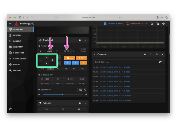
Use mainsail to move the tool carriage to find the first print heads select position.
-
The cam pin should enter the tool plate without bumping it.
-
There should be less than a 1mm gap between the tool plate and master plate.
-
Test this position by sending a locking command to the servo - in our case angle 120.
-
If the print head is picked up successfully make a note of the x/y positions - this is your select position for this print head.
-
See next step for finding the docking position.
-
If the tool carriage is bumped at any point you should re-home your X/Y axes to prevent skipped step errors.
-
-
-
With the print head selected from the previous step pull it out from its dock by moving the print head 100mm in the positive X direction.
-
Check that the print head is stable and secure on the tool carriage.
-
Use mainsail to move the print head back to its dock to find its docking position.
-
You'll find that the dock Y position may be slightly different to the select Y position.
-
The dock X position should be the same as the select X position.
-
Dock and release the print head by sending a release command to the servo - in our case angle 30.
-
When docked successfully make a note of the X/Y docking positions.
-
Repeat from the previous step to find the select and dock positions for the remaining print heads you have installed.
-
-
-
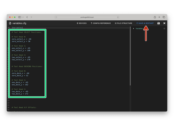
Enter your Select and Dock positions for the print heads in the variable.cfg file.
-
Note Tool Head 0 is the first Print Head, nearest the front of the printer.
-
Save and restart to allow the values to take effect.
-
-
-
If you have only the standard SO3 extruders installed you can skip this step.
-
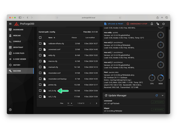
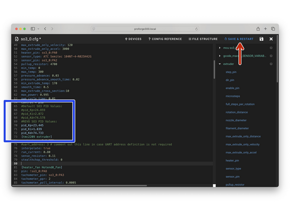
In the SO3_x.cfg files scroll down to the PID settings.
-
If you have a REVO print head installed comment out the SO3 PID values by adding # infront of them.
-
Activate the REVO PID settings by removing the # infront of them.
-
Do this for each print head config file where there is a REVO print head installed. Remember to save the file.
-
Restart when all SO3_x.cfg files have been modified.
-
The default PID values we have set should work well for you - but if you find your hotend heater temperature is not stable whilst printing you can tune these values by sending PID_CALIBRATE HEATER=extruder TARGET=200
-
-
-
Home X and Y.
-
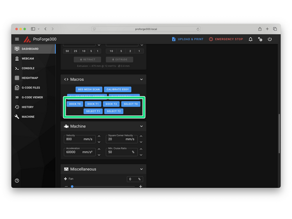
Use the select and dock macros to test print head swapping.
-
Always dock the current print head to it's dock before selecting another print head - not doing so will cause a crash!
-
-
-
Select the first print head.
-
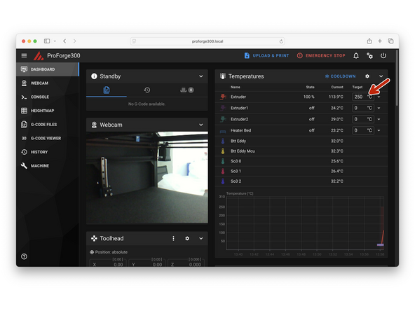
If default SO3 hotend, remove the silicone sock.
-
Heat the print head to 250C.
-
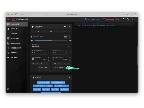
Send extrude command.
-
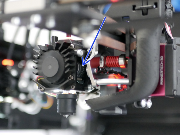
Check the that the drive gear is rotating anti-clockwise. Ensure a full 360 degrees of rotation takes place.
-
See next step for hot-tightening.
-
-
-
The REVO Print Heads do not need to be hot tightened.
-
Use the FRONT macro to bring the print head to a convenient position at the front of the printer.
-
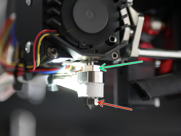
If you have the standard SO3 Print Head tighten the nozzle whilst the hotend is hot. Do this by using two spanners.
-
Hold with 8mm spanner
-
Tighten with 6mm spanner
-
Repeat from the previous step with all your print heads.
-
The Hotend will be hot enough to cause burns - be careful.
-
-
-
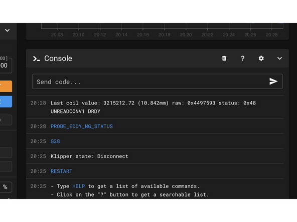
Check the status of the probe by sending: PROBE_EDDY_NG_STATUS
-
You should see something similar to this return back (you may need to send it twice):
-
Last coil value: 3189314.38 (-infmm) raw: 0x4409e8b (Not calibrated) status: 0x48 UNREADCONV1 DRDY or status: 0x0, everything is fine. If you see 0xffffffff or similar, there is a communication issue with the sensor. Look at your klippy logs for clues and check your wiring and configuration.
-
Firmware for the Eddy has been updated (02/05/2025) to allow for TAP probing. If you installed firmware before this date we recommend just installing the EDDY-NG packages by using Termius to SSH into the printer and sending the following commands. After installing this, the probe will also need new firmware flashed onto it. You will also need to upload the updated config files.
-
cd ~
-
git clone https://github.com/vvuk/eddy-ng
-
cd ~/eddy-ng
-
./install.sh
-
-
-
Select the first print head.
-
Send SET_KINEMATIC_POSITION Z=300 to move the bed without having to home it first.
-
Move the head to the front left, rear, and front right. Use an object as a spacer to check the nozzle-to-bed gap, and manually turn the Z motors to match the gap at all three points.
-
We want the bed to be trammed within around 5mm for the Eddy to work properly.
-
-
-
Before starting ensure that the flexplate is placed on the bed.
-
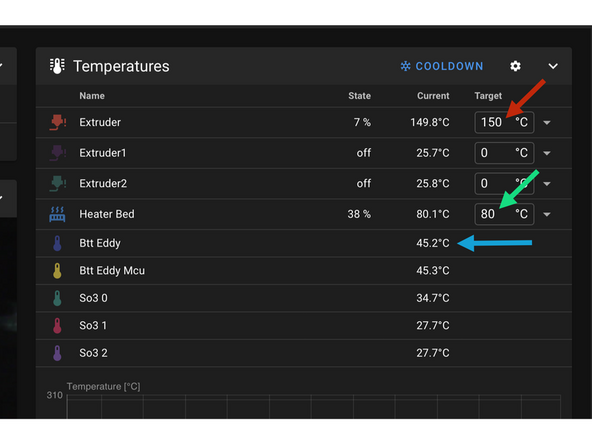
Heat first print head to 150C
-
Heat Bed to 80C
-
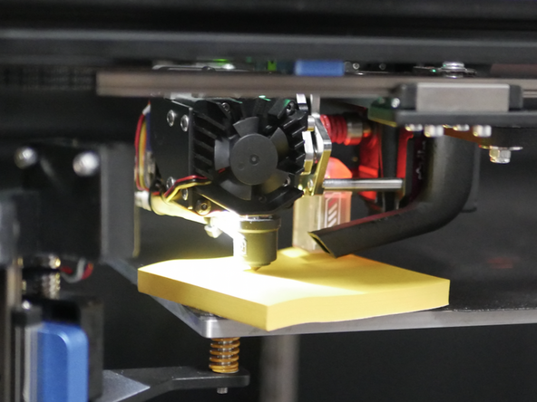
Move print head to the centre and bring the bed close to the print head so that the Eddy probe can also heat up.
-
Send SET_KINEMATIC_POSITION Z=300 to move the bed without having to home it first.
-
Wait for the Eddy probe temp to reach the mid 40's.
-
-
-
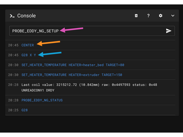
Before starting ensure the Eddy probes temperature has reached the mid-40's or higher. Next send the following commands:
-
G28 X Y
-
CENTER
-
Ensure the bed is at 80C.
-
PROBE_EDDY_NG_SETUP
-
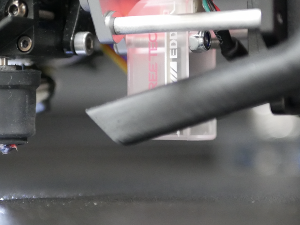
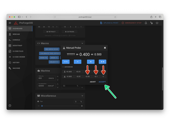
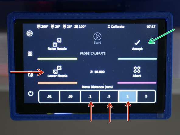
Use the pop-up modal to raise the bed until the nozzle grips the piece of paper. You can also do this from the touch screen display.
-
Press Accept when done.
-
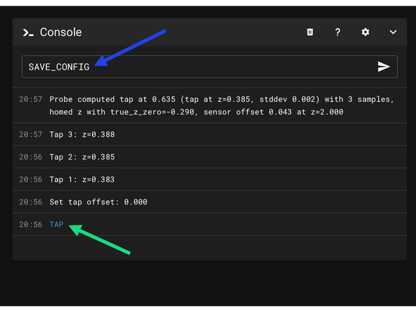
Send SAVE_CONFIG to save the changes.
-
-
-
Send the TAP command.
-
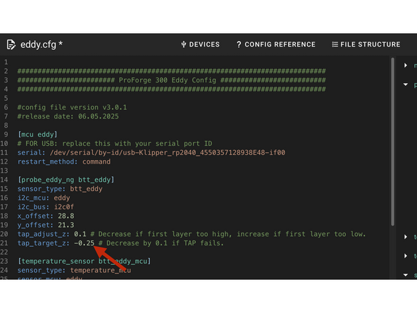
If TAP fails decrease tap_target_z in eddy.cfg.
-
Further FAQ + Trouble shooting tips can be found here.
-
-
-
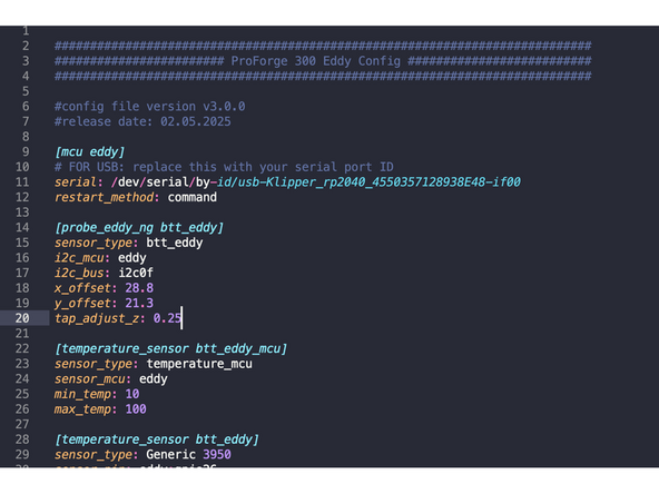
When printing if you find your first layer too high or low adjust the tap_adjust_z value in the Eddy.cfg file (Line 20).
-
This value is designed to account for the "flex" the print head experiences upon tapping.
-
If the first layer is too low, increase this value.
-
If the first layer is too high, decrease this value.
-
-
-
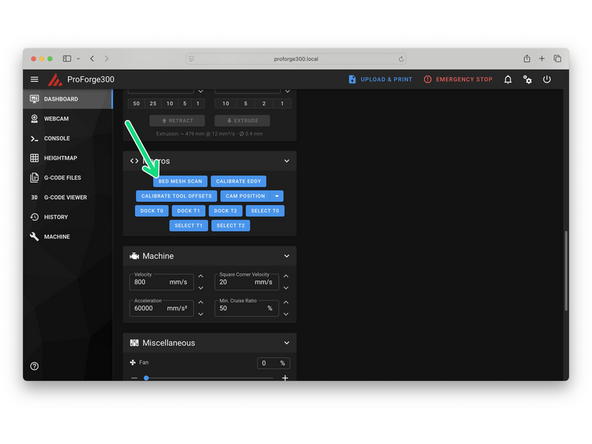
Dock the print head by sending DOCK_T0.
-
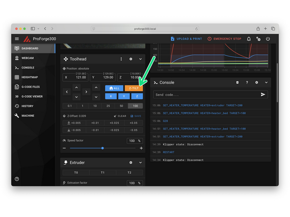
Ensure the printer is homed and send the Z_TILT_ADJUST command.
-
Eddy will probe the bed in three places. The bed will then automatically align itself to the gantry.
-
If Z-Tilt fails check that the platform is first manually trammed to within 5mm as this probing method can fail if the bed is skewed beyond this.
-
-
-
Again, ensure the print heads are all docked.
-
It's important that whenever you run a bed mesh scan that the print heads are docked.
-
Send BED_MESH_SCAN to start the scan.
-
The probe will rapidly scan and generate a 900 point mesh of the bed - that is not a typo.
-
-
-
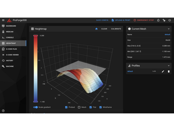
Go to Heightmap in Mainsail to view the bed scan.
-
Check for any anomalies.
-
Although the Aluminium bed itself has a tolerance of 0.1mm, the addition of the magnetic sticker and flexplate will affect this.
-
The mesh can be saved and called upon before starting a print, however we recommend (and by default it is setup this way) that the printer will generate a new mesh before the start of each print to guarantee a perfect first layer.
-
-
-
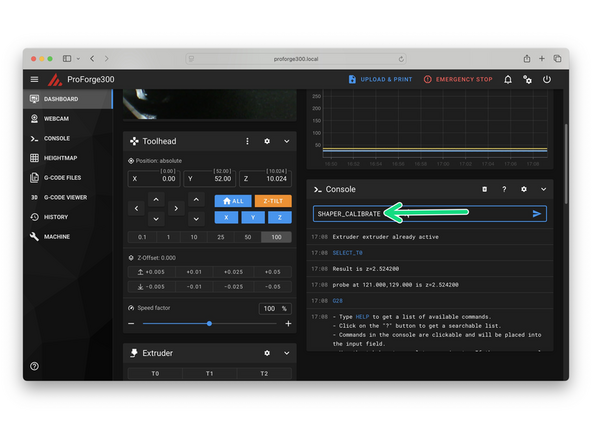
With the first print head selected use the CENTER macro to center the print head.
-
Send the following command:
-
SHAPER_CALIBRATE
-
The print head should oscillate in the X and then Y direction.
-
Once the calibration has completed running, send SAVE_CONFIG.
-
-
-
If you run into any errors or bugs please report them to info@makertech3d.com
-


Cancel: I did not complete this guide.
3 other people completed this guide.
