Difficulty
Moderate
Steps
18
Time Required
- Linear Rail Upgrade 18 steps

In Progress
This guide is currently being written. Reload periodically to see the latest changes.
Quiz
0
-
-
Check that you have all of the following:
-
3D Printed Parts (x4)
-
Rails (x4)
-
Fastener pack
-
5x8 Coupling
-
M4 Threaded Inserts (x11)
-
You will also need (not included):
-
Allen keys, Drill with metal bits (2mm/3mm), Side Cutters, Pliers, Soldering Iron (for threaded inserts)
-
-
-
Begin by disassembling the platform from the base.
-
Do this by first untying the belt from the platform.
-
Then remove the heated bed and place it to one side, you don't need to disconnect its wiring.
-
If you have the Pi Camera installed, unmount it also, again you don't need to disconnect it from the pi board.
-
Finally, remove the old HDPE linear guides holding the platform in place.
-
The platform should now be free for the next step of drilling the holes for the linear rails.
-
-
-
Next, remove the tool carriage and Y-belt from the gantry. Do not cut the belt, it will be re-used.
-
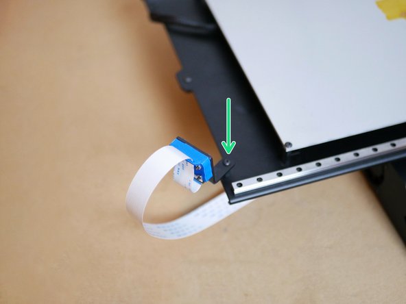
Free the y-endstop from the gantry.
-
The lead screw bracket at the top of the printer can also be removed, this part can be disregarded as it won't be re-used.
-
Disconnect the y-motor from its cable.
-
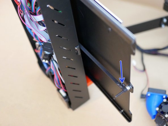
Use side cutters to break the cable ties holding the cables to the gantry.
-
Free the lead screw coupling from the z-motor shaft.
-
Finally remove the HDPE linear guides from the gantry and the entire gantry part should now be free.
-
-
-
If you have an extruder installed on the vertical pillar, remove it now.
-
Next, unfasten the bolts connecting the pillar to the support bracket at the top of the pillar.
-
Remove the the motor bolts at the bottom of the pillar.
-
The pillar should now come free.
-
-
-
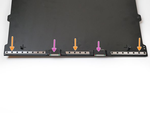
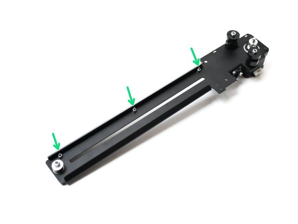
Use a 2mm metal drill to create 3 holes on either side of the platform.
-
Place one of the 40cm rails on the platform, 4mm +/-1mm from the edge.
-
Use a pencil to mark out where you are going to drill.
-
Secure the rail as shown with three M2 x 10mm bolts and M2 Nyloc Nuts
-
Be very careful with the carriage, either secure or remove them very carefully. If they fall off and are hit, the ball bearings inside them will escape!
-
-
-
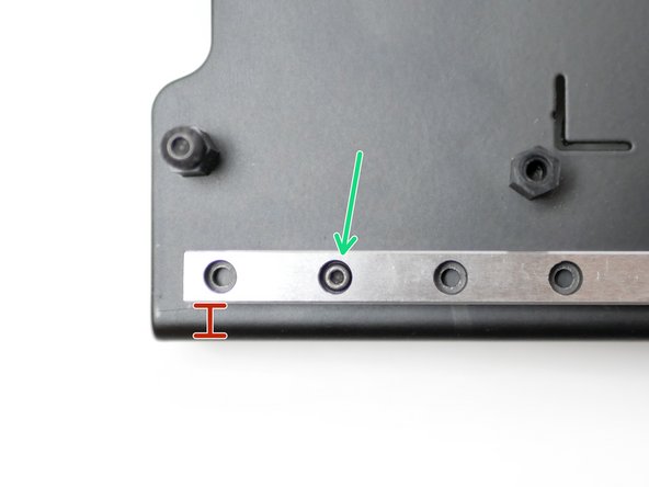
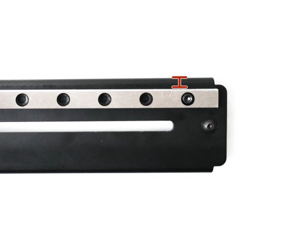
Use a 3mm bit to drill three holes into the gantry.
-
The rail should be fitted 5mm from the top edge of the gantry.
-
Secure with M3 x 12mm Cap and M3 Nyloc Nut
-
-
-
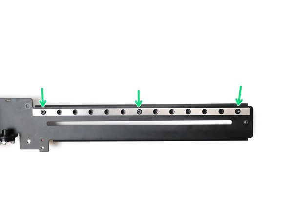
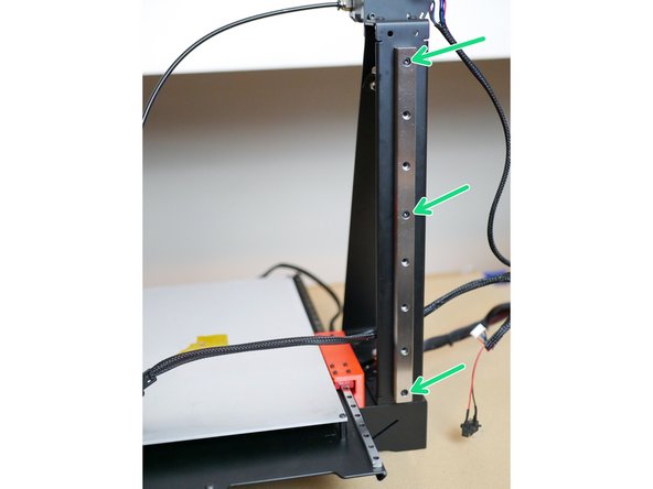
Align the thicker 15mm rail to the centre of the pillar and create marks for three holes.
-
Drill three 3mm holes into the pillar.
-
Secure the rail with three M3 x 12mm cap bolts and M3 nyloc nuts.
-
Re-install the z-pillar when done.
-
-
-
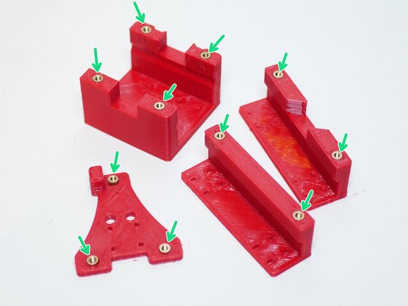
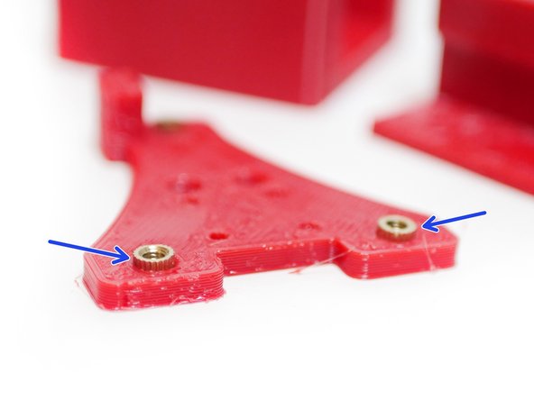
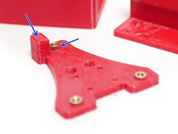
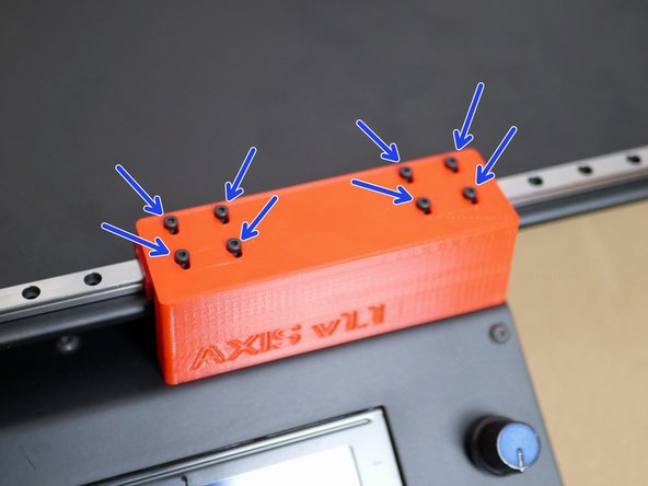
Using a soldering iron push the threaded inserts into the 3D printed parts as shown.
-
M4 Threaded Insert
-
Note that the inserts on the Tool Carriage part need to protrude out on the side shown.
-
-
-
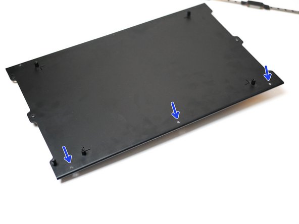
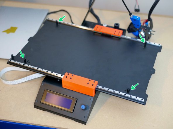
Begin by installing the two 3D printed parts to the Base with two M4 x 6mm Bolts.
-
Next line up the linear rail carriages on the platform with the holes on the 3d printed brackets.
-
Secure the platform to the brackets using M2 x 6mm cap bolts.
-
Double check you have the correct orientation, the heated bed cable relief mount should be in the top left.
-
-
-
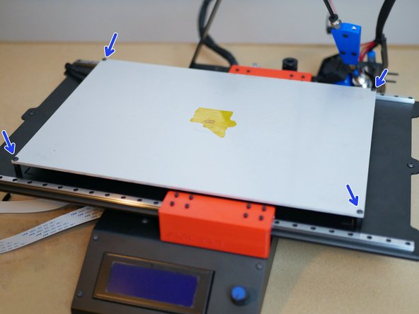
A heated bed is required for this upgrade to properly work.
-
The heated bed needs to be raised 5mm before it can be installed. To do this we replace the 10mm stand-offs with 15mm ones.
-
With the 15mm stand-offs installed, re-mount the heated bed.
-
-
-
Re-install the belt by first wrapping it around the pulley on the motor and then feeding it in through the rear bracket and around the bearings.
-
You will need to use a pen to guide the belt around the bearings.
-
Secure the belt to the bolts on the ends of the platform.
-
Re-attach the Pi-cam if you have that upgrade.
-
-
-
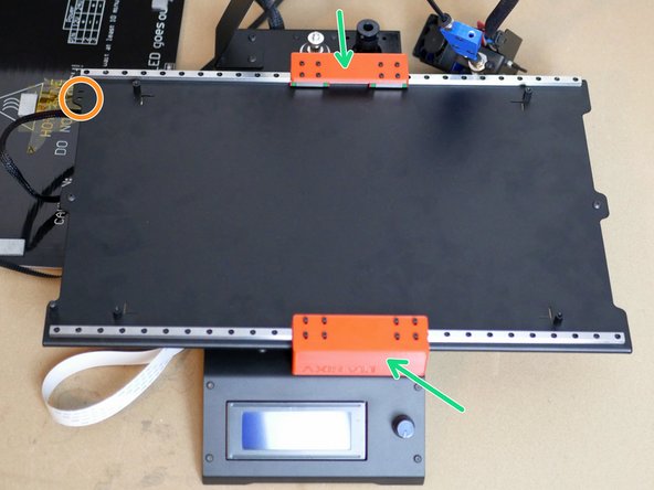
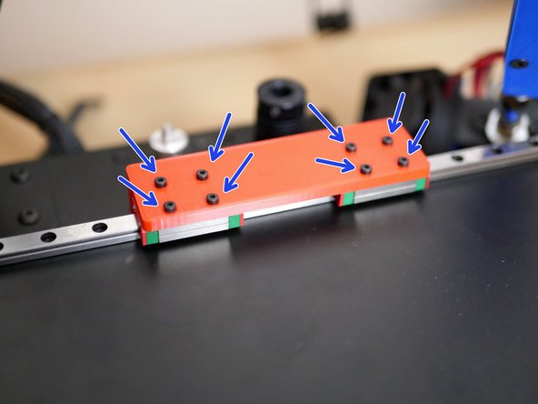
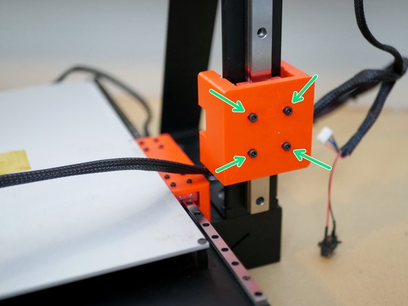
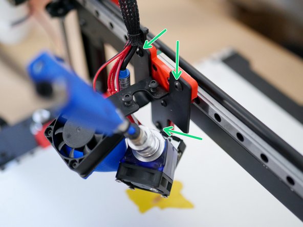
Fix the gantry carriage to the Z-Rail as shown with four M3 x 8mm cap head bolts.
-
Note the orientation of the carriage. The side with the small insets should point towards the rear of the printer.
-
-
-
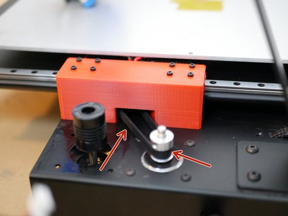
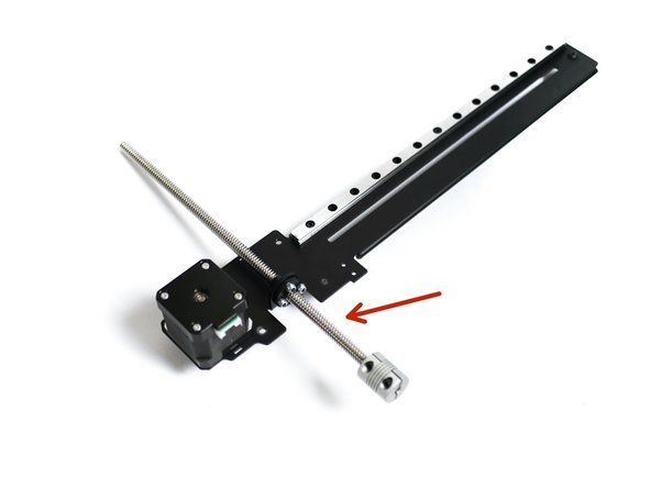
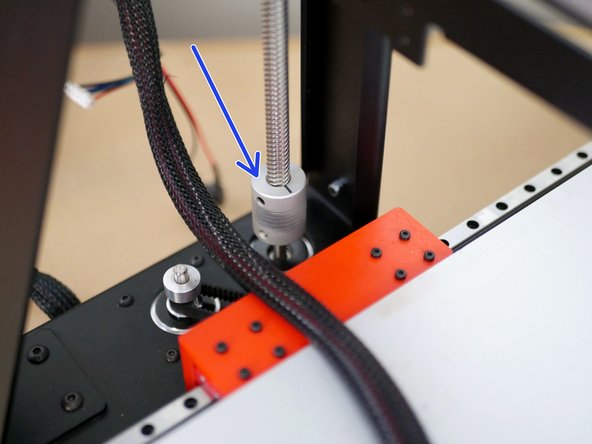
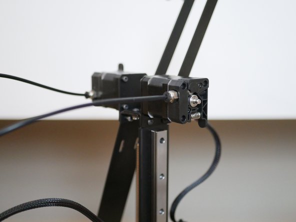
Re-attach the the lead screw to the gantry.
-
Next fix the coupling to the z-motor shaft.
-
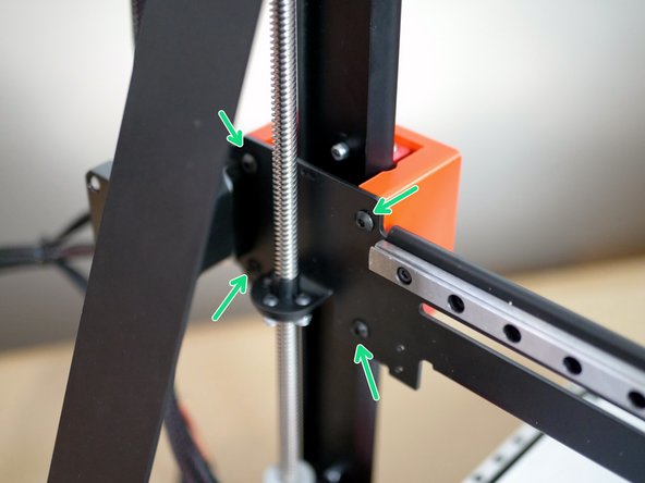
Finally, fix the gantry to the carriage with four M4 x 6mm bolts.
-
You can also now reattach the end stop and cables.
-
-
-
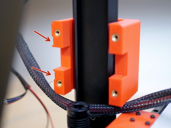
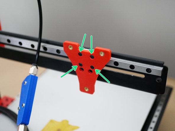
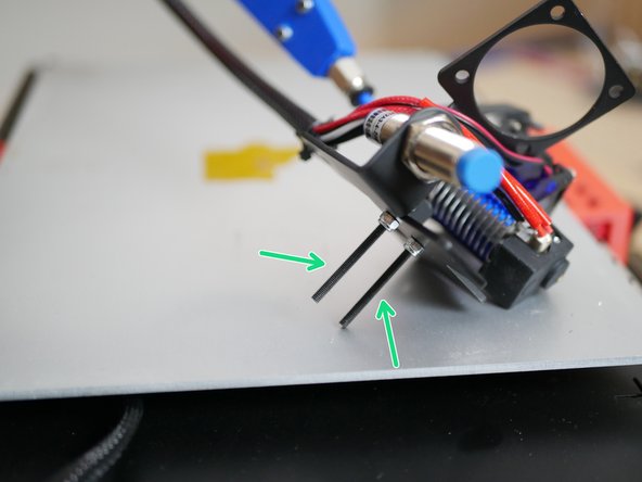
Fix the 3D printed tool carriage to the gantry rail.
-
M3 x 6mm button head
-
-
-
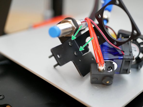
Replace the M3 x 25mm bolts on the metal tool carriage with the two M3 x 35mm bolts.
-
-
-
Mount the metal tool carriage onto the 3D printed one with three M4 x 6mm bolts.
-
-
-
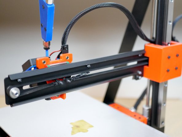
Finally, re-attach the belt and the extruder.
-
-
-
Printing should be the same as before, the only thing to be aware of is that the z-height has been reduced by approx 5mm.
-
Along with the stability improvements you should also now be able to run the AXIS at higher speeds.
-
You can see it printing here.
-