-
-
In this stage the steps marked with "DSE:" in the title are for the installation of the Dual Switching Extruder.
-
If you are building a single extruder setup you can ignore these steps.
-
-
-
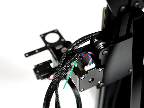
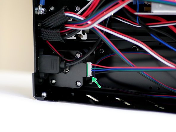
Connect to the Y-Endstop its cable.
-
Feed the cable around the Y-Motor.
-
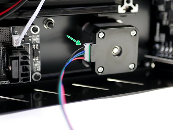
Connect a motor cable to the Y-Motor.
-
-
-
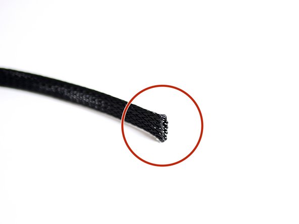
Cut 60CM of the braided cable sleeving.
-
Melt the ends with a lighter to stop them from fraying out.
-
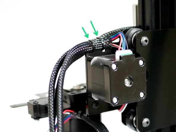
Feed the sleeving onto both the Endstop and Motor cables.
-
-
-
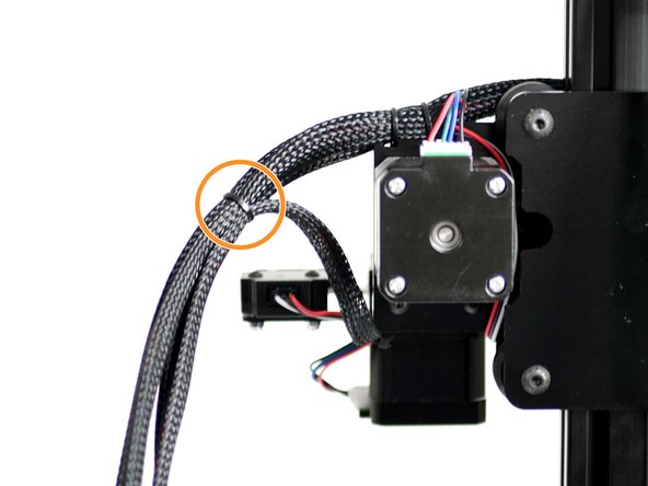
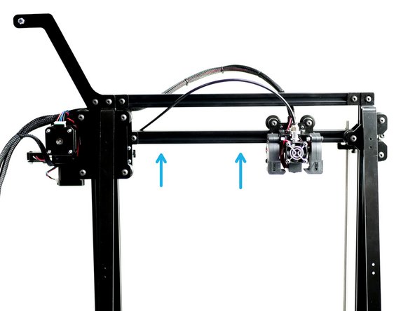
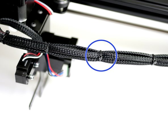
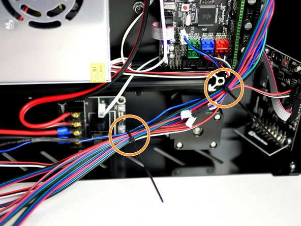
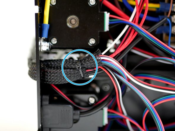
Cable tie the cables to the Z-Carriage bracket.
-
Use a second cable tie to connect the cables from the gantry to the extruder's cables.
-
-
-
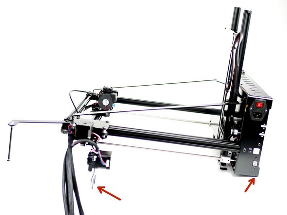
Raise the Gantry to its highest position.
-
Carefully lay the machine down on its side like shown.
-
-
-
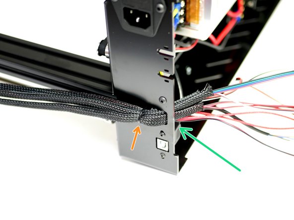
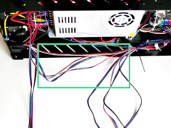
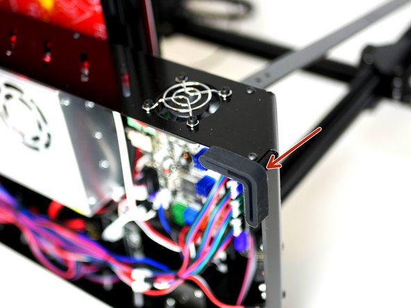
Feed all of the loose cables through the hole on the back of the Base.
-
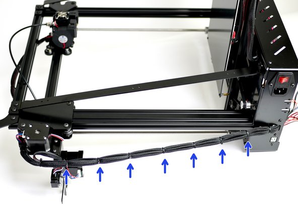
Cable tie the cables to the Base.
-
Use multiple cable ties to create a single stem of all the cables.
-
-
-
If building with the Dual Switching Extruder upgrade this is Hotend #1 (on the left).
-
Find the group of cables from the Hotend.
-
Hotend Heater Cables
-
Thermistor Cables
-
Hotend Fan Cables
-
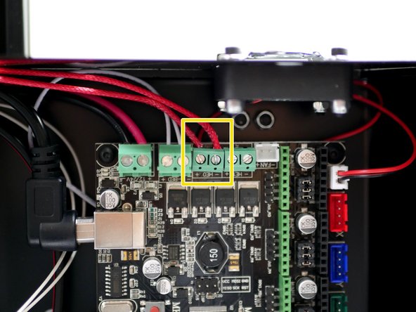
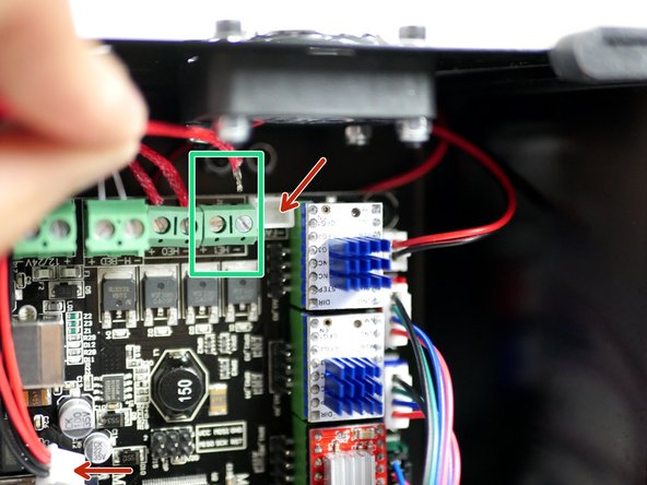
Connect the Hotend heater cables to the HE0 terminal on the control board.
-
The +/- position of the cables is not important. You may need to unscrew the board from its mounts to properly access it.
-
Connect the Thermistor cables to the TH1 connector on the board.
-
-
-
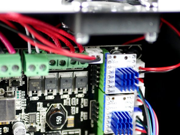
Connect the Hotend #2 (on the right) heater cables to the electronics board.
-
Unplugging the print fan cable for the board should give you better access.
-
If you're struggling to the get the cables in, removing the electronics board from the base will give you better access to the terminals.
-
Connect the Hotend's thermistor to the electronics board (TH2).
-
-
-
Cable tie together the Hotend heater and thermistor cables.
-
Loop and cable tie the excess cable.
-
Keep the cable ties a short distance in from the ends so as not to create any sharp bends in the cables.
-
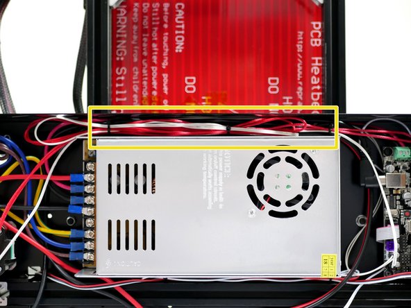
Tuck the cables in between the side panel and power supply.
-
-
-
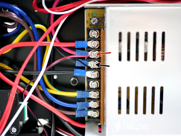
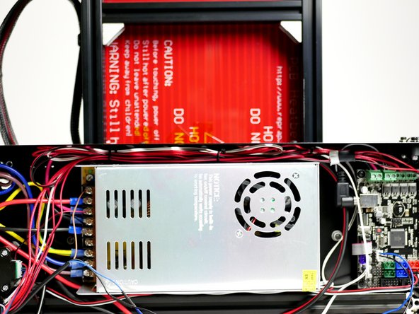
Connect the Hotend fan directly to the power supply.
-
Red cable to positive.
-
Black cable to negative.
-
You can cut the cable down for a better fit but remember to leave some spare if you plan on later upgrading to the Dual Switching Extruder.
-
-
-
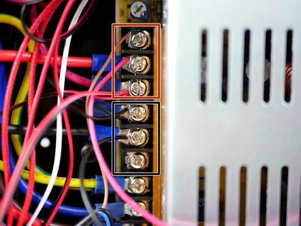
As before connect the Hotend's fan cables directly to the power supply terminals.
-
Red to Positive
-
Black to Negative
-
-
-
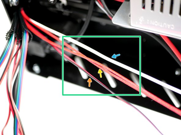
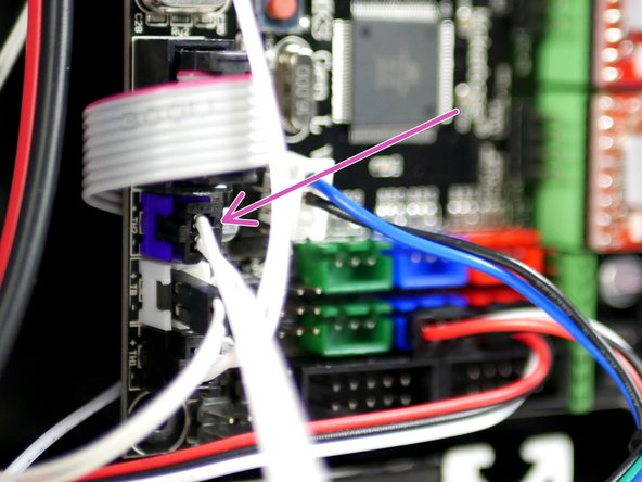
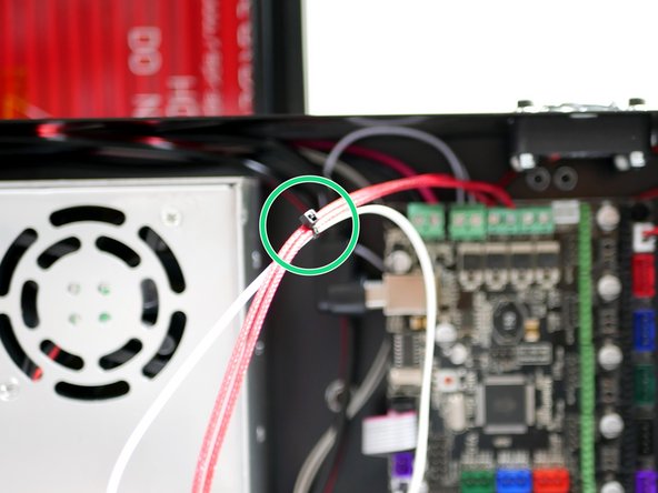
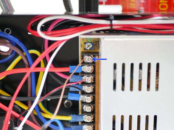
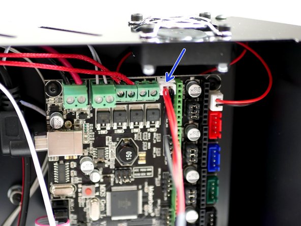
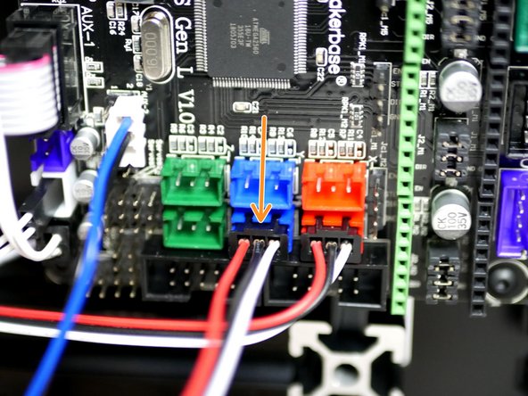
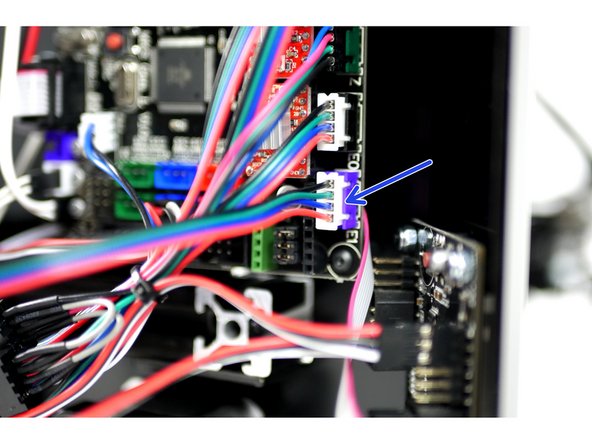
Connect the brown wire from the probe directly to a positive terminal on the power supply.
-
Fix the connector to the electronics board as shown in the second image.
-
-
-
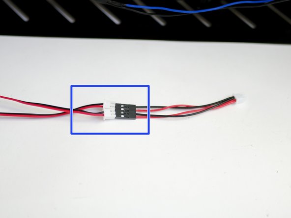
Connect both cables form the print fans to the print fan adapter.
-
Black to Black and Red to Red
-
Connect the other side of the adapter to the electronics board.
-
-
-
Cable tie the print fan cables to the Hotend cables and tuck away.
-
-
-
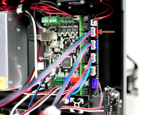
Find the pair of cables for the Y-Motor and Y-Endstop.
-
Connect the Y-Endstop to the board (Y+).
-
Connect the Y-Motor to the Board.
-
-
-
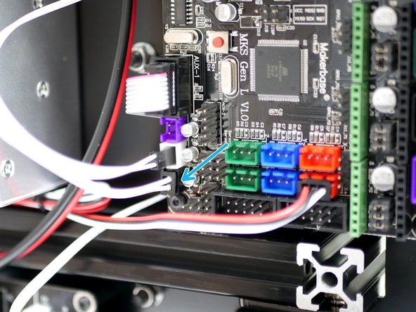
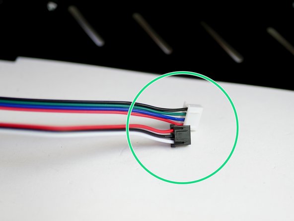
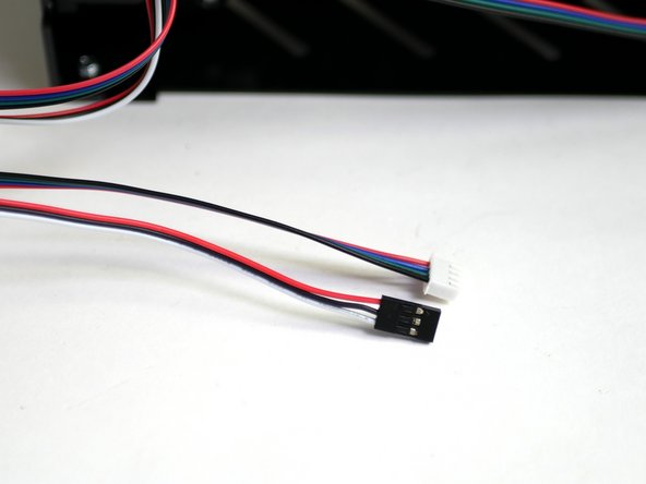
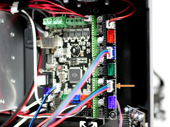
Find the Extruder motor cable and filament sensor cable.
-
Connect the Extruder Motor to the E0 position on the board.
-
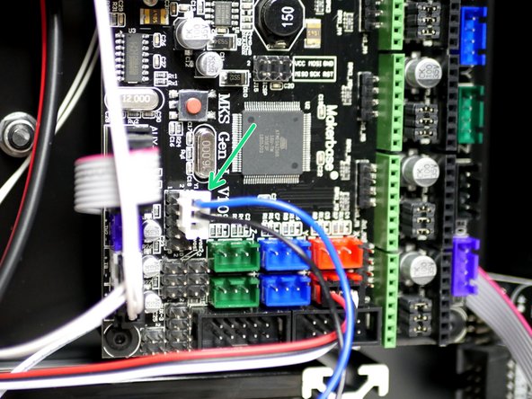
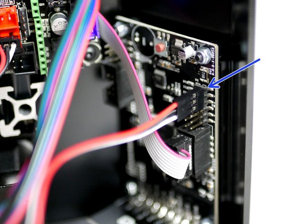
Connect the filament sensor to the Touch Screen.
-
-
-
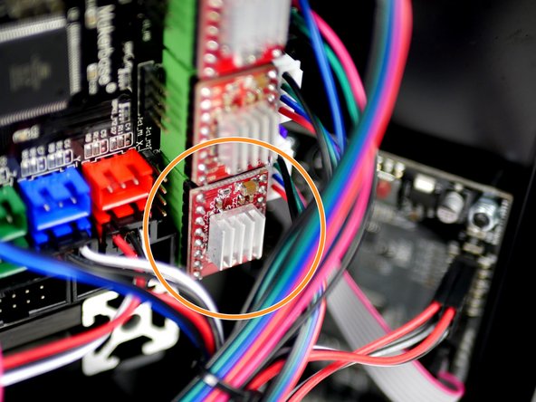
Connect the 2nd extruder motor cable to the main board in the E1 position.
-
Connect the 2nd filament sensor cable to the touch screen.
-
-
-
Connect a motor cable to the X-motor.
-
Connect the X-motor to the control board.
-
-
-
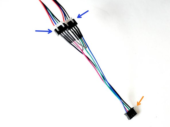
Connect motor cables to both Z-motors.
-
-
-
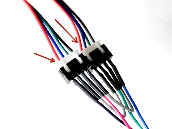
Connect the other ends of the motor cables to the dual z-motor adapter.
-
Make sure the the red cable is on the same side of the connector for both of the Z-motor Cables. If they are different swap with a cable from one of the other motors.
-
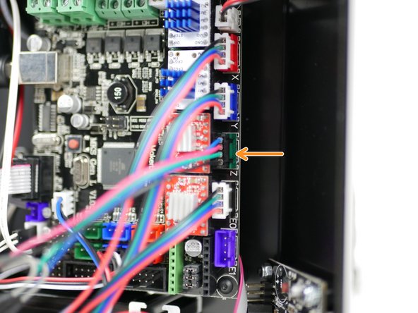
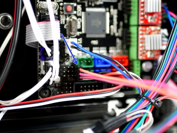
Connect the adapter to the Z-motor position on the control board.
-
-
-
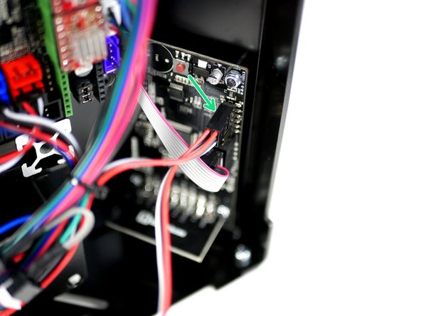
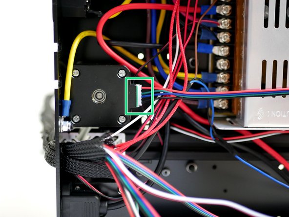
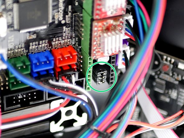
Connect the servo cable to the electronics board like shown.
-
-
-
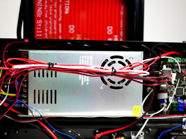
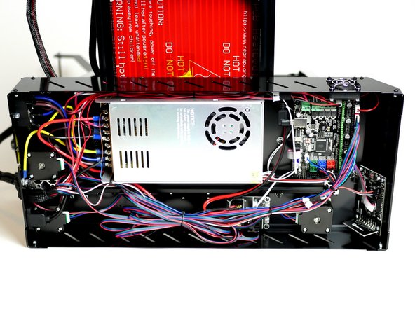
Use cable ties to tidy up the cables like shown.
-
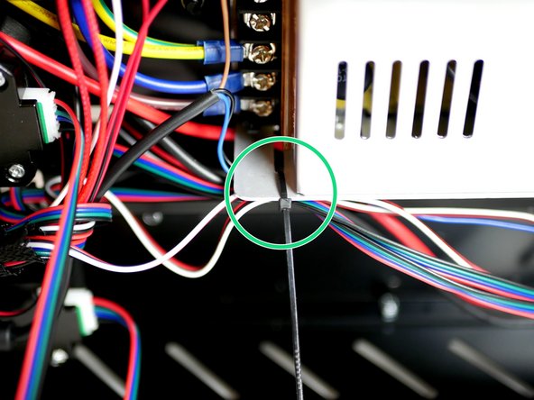
Lay the cables out and cable tie the shorter bunch to the side of the power supply.
-
-
-
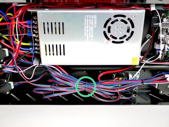
Loop up the remaining longer cables and cable tie together.
-
Cable tie the cables near the entry hole on the Base.
-
Make sure there are no sharp bends in any of the cables.
-
-
-
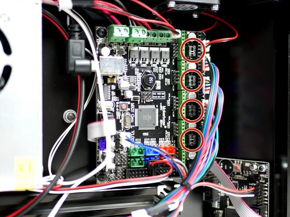
Before installing the stepper drivers check that there are three jumpers at each of the stepper positions, like shown in the image.
-
Some boards will have these already installed, others won't. They should be in a small bag in the mainboard packaging.
-
-
-
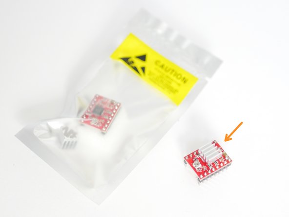
Prepare two of the A4988 Stepper Drivers by removing them from their packaging and sticking the heatsink to the black chip.
-
Make sure that the heatsink is not touching any of the pins. Orient the fins of the heatsink as shown.
-
The kit also includes one spare A4988 Stepper Driver.
-
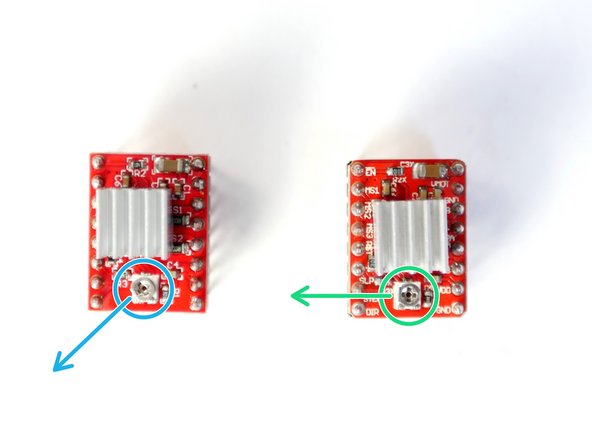
Z-Axis Stepper: Adjust the trimpot so that flat side is pointing towards the bottom left corner as shown in the second photo.
-
E-Axis Stepper: Adjust the trimpot so that flat side is pointing left as shown in the second photo.
-
Fix the two Stepper Drivers onto the the control board as shown in the Z and E0 positions.
-
Make sure that the screw trimpot side of the stepper drivers is pointing towards the touch screen. Installing a stepper driver the wrong way round will destroy it.
-
-
-
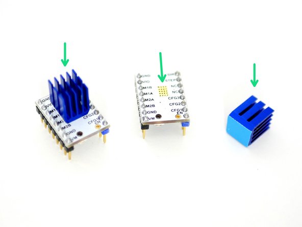
Prepare the two TMC2100 stepper drivers by removing them from their packaging and sticking on the Heatsinks as shown in the first image.
-
Make sure the heatsink is not touching any of the pins.
-
Orient the fins of the heatsink as shown.
-
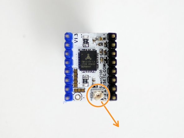
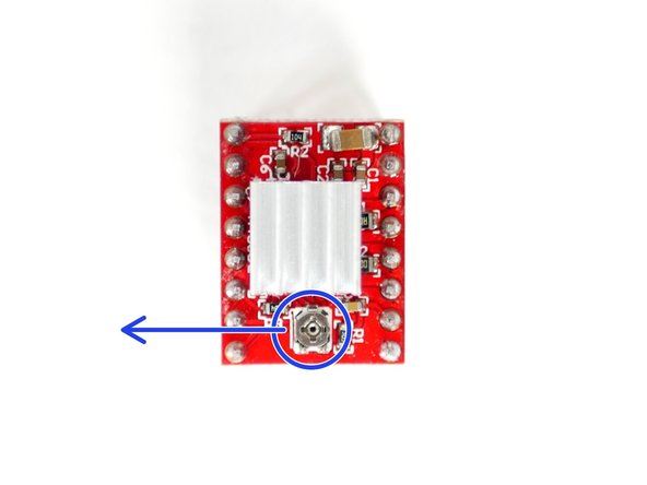
Adjust the trimpot so that flat side is pointing towards the bottom right corner as shown in the second photo.
-
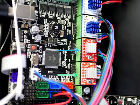
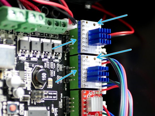
Fix the two TMC2100 Stepper Drivers to the X & Y Positions.
-
When installing, match the orientation of the drivers as shown in the second image.
-
Installing a stepper driver the wrong way round will destroy it.
-
If you're building the Proforge 2 use the red A4988 drivers here with the flat side of the trimpot facing the bottom left corner, as shown for the Z-axis stepper in the previous step.
-
-
-
As before repare the A4988 Stepper Driver by sticking the heatsink to the black chip on the driver.
-
Make sure that the heatsink is not touching any of the pins. Orient the fins of the heatsink as shown.
-
Adjust the trimpot so that the flat side is facing left, like shown in the second image.
-
Check that you have 3 jumpers installed like shown in the second image.
-
Fix the stepper driver onto the electronics board, matching the orientation shown in the third image.
-
Installing a stepper driver the wrong way round will destroy it.
-
-
-
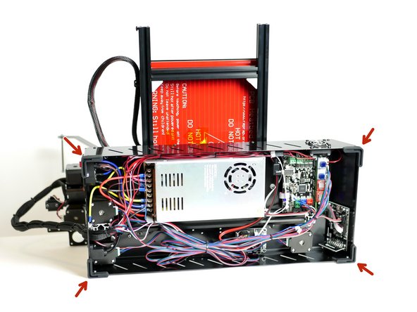
Fix onto the four corners the four rubber feet.
-
-
-
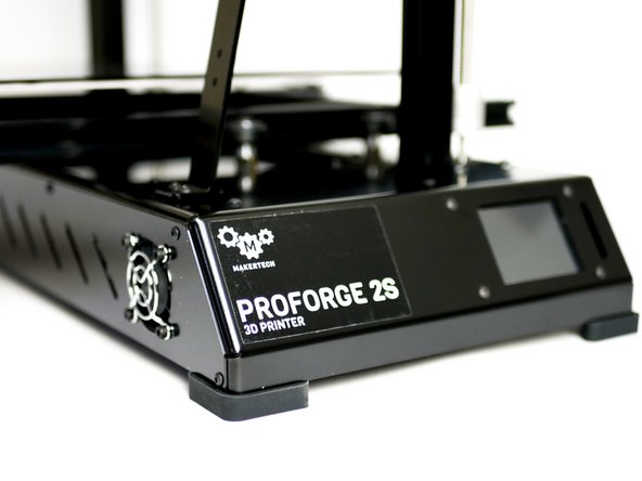
Apply to the front of the machine the Proforge 2S Sticker.
-
-
-
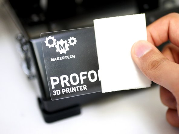
Before starting make sure the flexplate surface is clean.
-
Peel away the backing from the right side of the surface sticker.
-
Fix the sticker onto the edge of the flexplate making sure to carefully align it with the top and bottom edges.
-
Pull away the backing paper and press down the sticker.
-
Place the flexplate on to the centre of the platform.
-
-
-
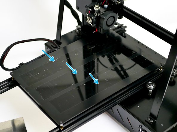
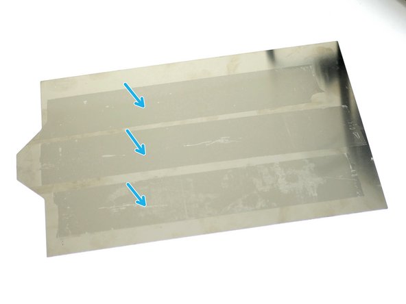
Sometimes during a print the nozzle might bump a part of your print and normally this might not be enough to affect the print overall, however this may be enough to cause the flexplate to slide and ruin the print.
-
To prevent this we can put some tape on both the platform and the back of the Flexplate to create more friction between the surfaces.
-
-
-
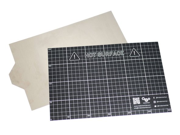
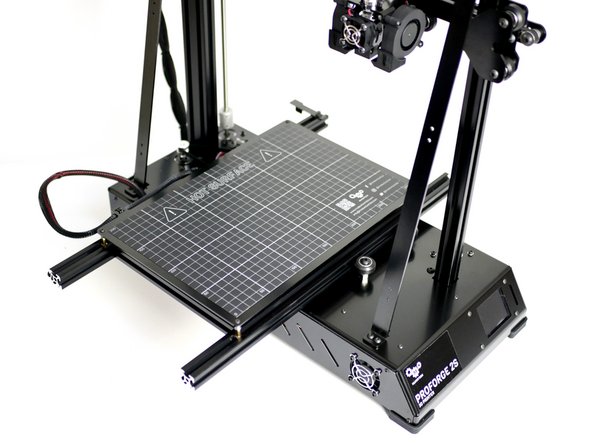
Before starting make sure the metal surface is clean.
-
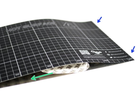
Partially remove the backing paper from the short side of the Print Surface Sticker.
-
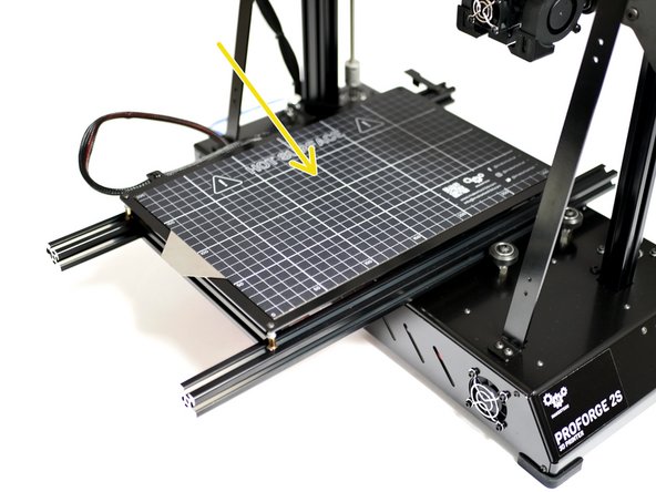
Align the sticker with either the left or right side and evenly apply pressure as you fix the sticker onto the platform.
-
Aim to apply centrally on the platform, keeping an equal gap from all of the edges.
-
-
-
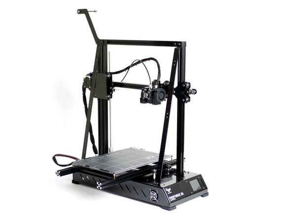
Congratulations! You've completed the mechanical build of the Proforge 2/2S 3D Printer!!
-
If you are building the Proforge 2/2S with the Dual Switching Extruder Upgrade, continue the build with the DSE guide here.
-