
-
-
If you are building the Proforge 2/2S with the Dual Switching Extruder, complete the build with stages 5, 6 and 7 of the Dual Switching Extruder Guide.
-
-
-
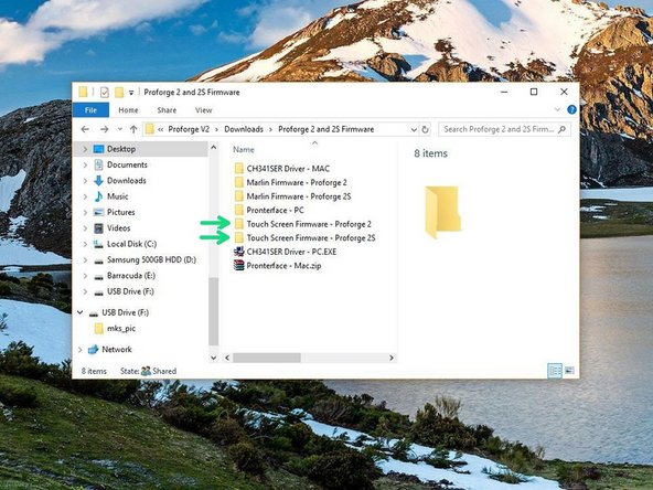
Download the GitHub repository for the Proforge 2S. Inside will include the following that you will need for this stage of the build:
-
Marlin Printer Firmware
-
Touch Screen Firmware
-
USB Drivers
-
Also download pronterface:
-
Pronterface- Printer Control Software
-
-
-
You will also need to download and install the Arduino IDE.
-
We recommend downloading V1.8.1, as this is what is used in this guide.
-
-
-
-
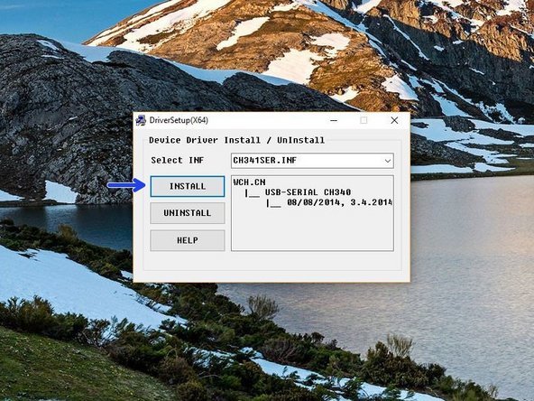
In the USB driver folder on PC double click on the CH341SER Driver - PC.EXE file. On MAC see the Readme.pdf file in the Mac folder.
-
You may need to right click, "run as admin" to open.
-
Once open, click INSTALL.
-
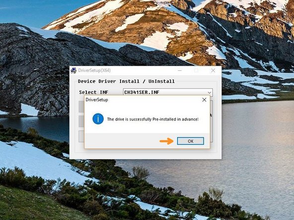
Once done, you should get a success message, click OK and close the programme.
-
-
-
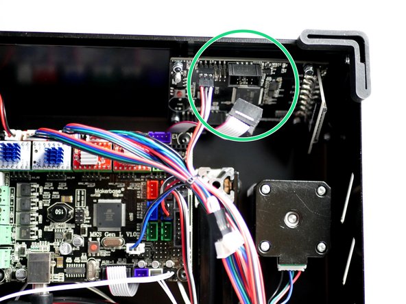
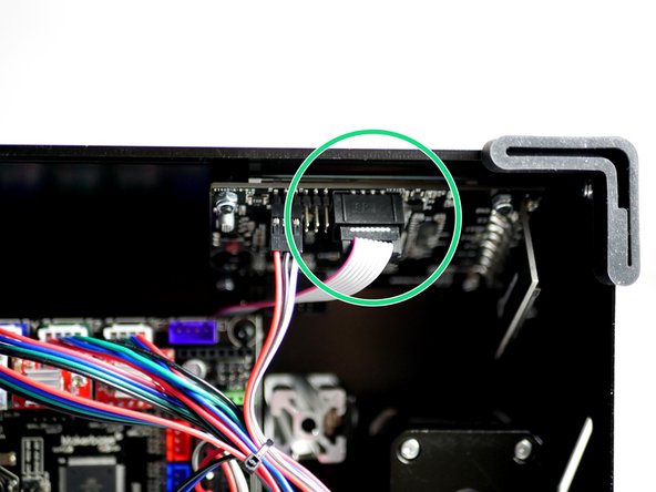
Disconnect the touch Screen display from the control board.
-
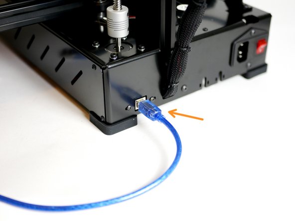
Connect the printer to your computer via the blue USB cable.
-
-
-
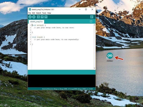
Open the Arduino IDE that you installed in step 3.
-
Right click, Run as Admin
-
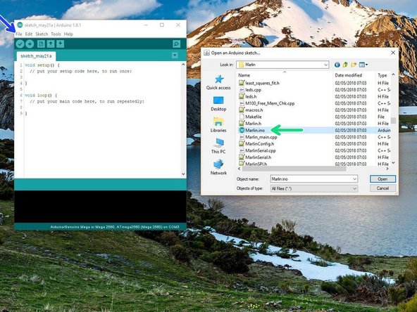
Go to File -> Open
-
Navigate to Marlin -> Marlin.ino in the Printer Firmware folder that you downloaded.
-
Check you have downloaded the correct firmware depending on whether you are building the Proforge 2 or 2S.
-
-
-
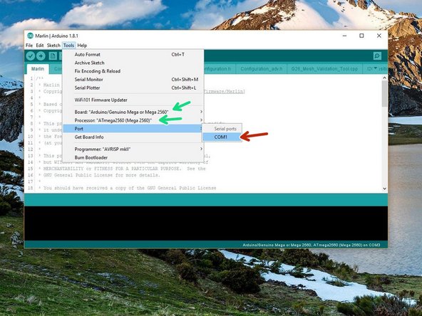
Go to Tools -> Port and select the port the Proforge 2/2S is connected to.
-
There should only be one but if you have others disconnect the Proforge from your computer to deduce the correct COM port.
-
Set the Board and Processor to Mega 2560
-
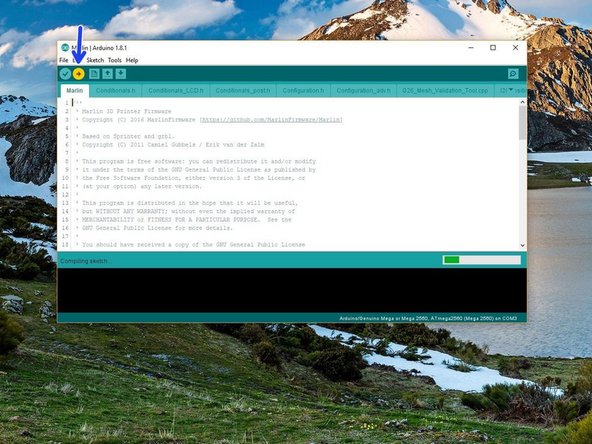
Click upload.
-
-
-
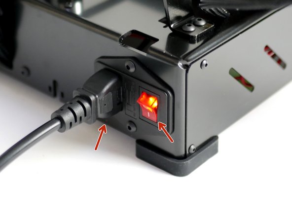
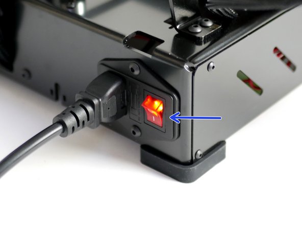
Once the firmware has done uploading keep the USB connected and power up the Proforge 2/2S via the mains power cable.
-
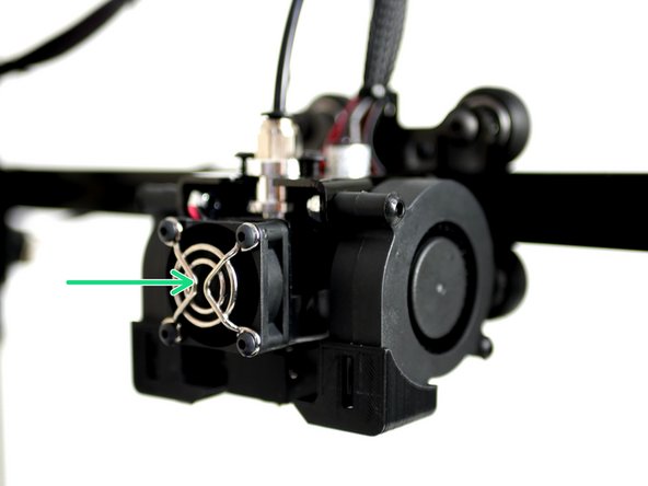
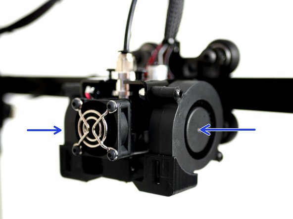
Check that the Hotend fan is spinning.
-
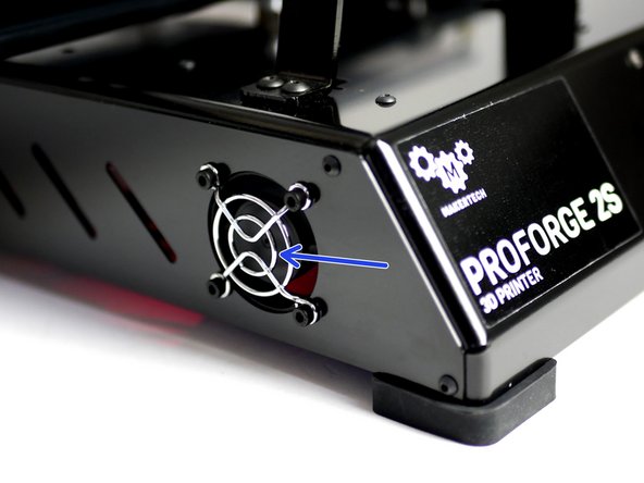
Check that the electronics fan is also spinning.
-
-
-
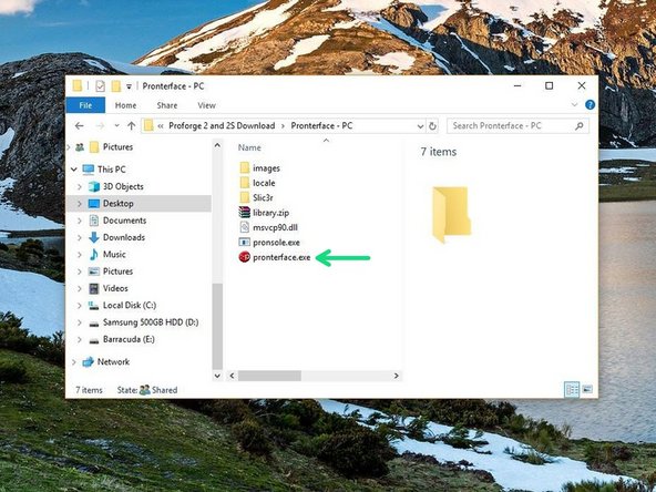
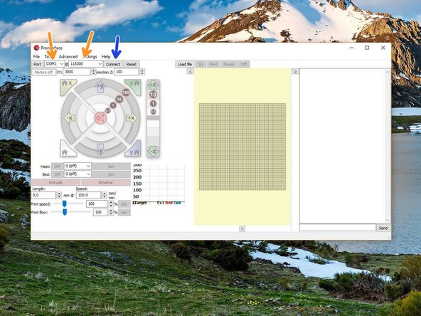
Launch Pronterface directly from it's folder.
-
Select your COM port, and set the baudrate to 250000.
-
Connect to the Proforge 2/2S.
-
-
-
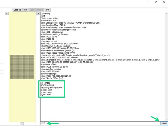
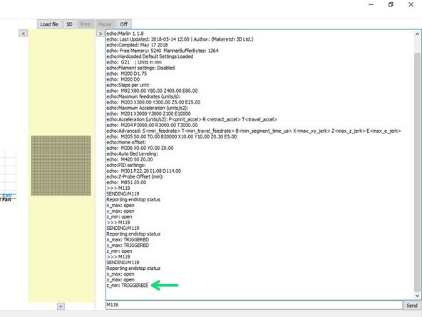
Once connected send an M119 command through the terminal on Pronterface.
-
It should read back open for both the endstops and probe.
-
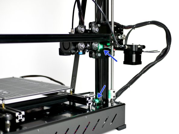
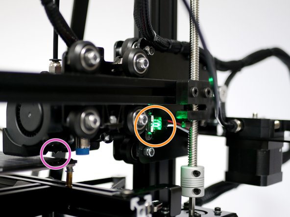
Move by hand the axes so as to trigger the X & Y endstops. A green light should shine.
-
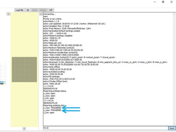
Send the M119 command again - the X & Y endstops should return with a TRIGGERED message.
-
-
-
Whilst holding a metal object under the probe (a red light should shine) send the M119 command.
-
Pronterface should return: z_min: TRIGGERED.
-
Disconnect the USB Cable and power off the printer from the mains.
-
-
-
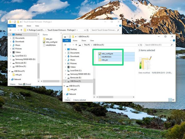
Copy the contents of the Touch Screen Firmware folder (depending on whether you're building a Proforge 2 or 2S) to the included SD card.
-
Make sure only the contents of the folder is on the SD card.
-
-
-
Make sure the printer is powered off and disconnected from your computer.
-
Reconnect the Touch Screen to the control board.
-
-
-
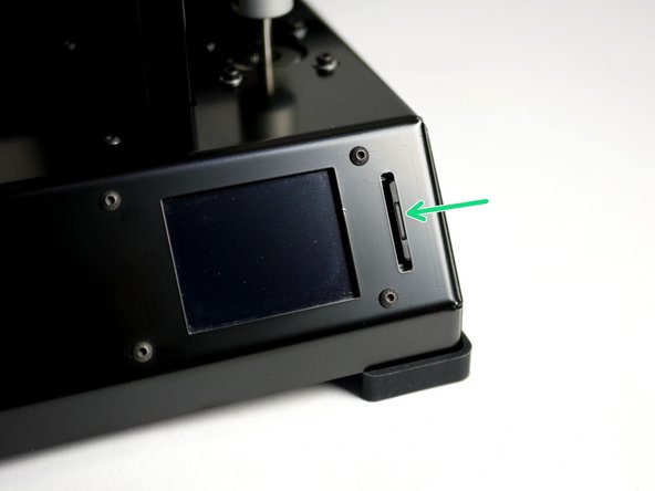
Insert the SD card with touch screen firmware on it.
-
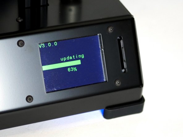
Power up the Proforge 2/2S. The Touch Screen display should now power up also and begin installing the firmware.
-
Wait for the install on the Touch Screen to finish, it should only take a minute.
-
-
-
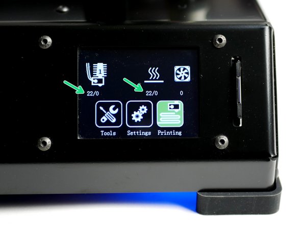
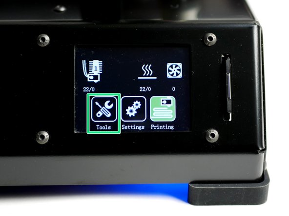
Once done uploading you should have a screen that looks like this.
-
Check that you are getting correct temperature readings (Celsius), ie. room temperature.
-
-
-
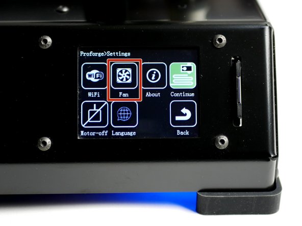
Go to Settings -> Fan
-
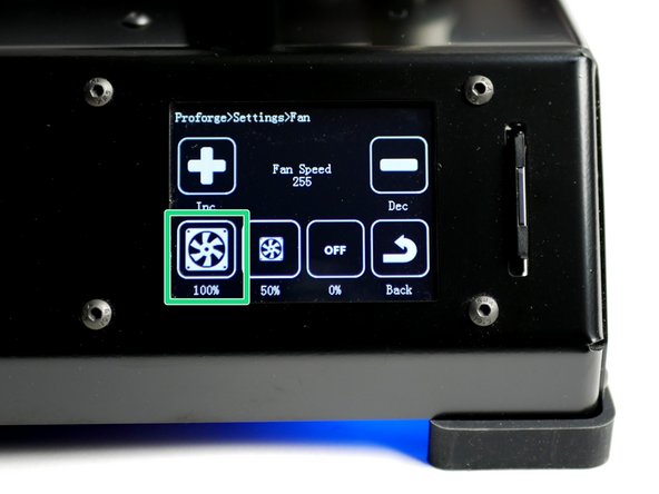
Power up to 100%
-
Both of the blower fans should start running.
-
-
-
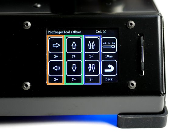
X-Axis: Pressing the left arrow will move the bed to the right, and vice versa.
-
This is correct as the nozzle position has moved in a negative direction relative to the platform.
-
Y-Axis: Pressing the down arrow will move the Hotend towards the front of the printer and vice versa.
-
Z-Axis: Pressing the double up arrow will move the gantry up and vice versa.
-
You will not be able to move to a positive position from your original starting position - this is normal.
-
If an axis moves in the opposite direction double check that you have uploaded the Proforge 2S Firmware if you are building with TMC2100 drivers. If you've uploaded the correct firmware and are still getting incorrect motion, see next step.
-
If an axis is not moving power down the printer and check steps 19, 20 and 21 relating to the stepper drivers and stepper driver jumpers.
-
-
-
If an axis from the previous step moves in the wrong direction power off your printer and disconnect the touchscreen.
-
In the aruino IDE go to the "configuration.h" tab.
-
Scroll down to lines 855-858. (Go to File -> Preferences and check "Display line numbers")
-
#define INVERT_X_DIR true
-
Change true to false to switch the motors direction depending on the problem axis (X, Y or Z).
-
Re-upload the firmware.
-
Once uploaded, connect back the touch screen and power up the printer from the mains again.
-
Continue from the previous step.
-
-
-
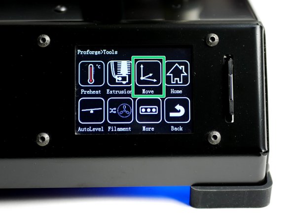
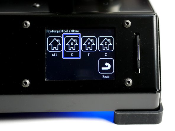
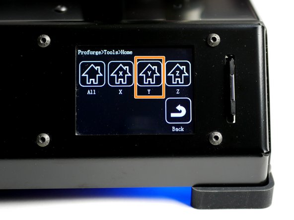
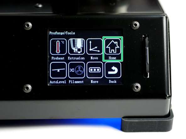
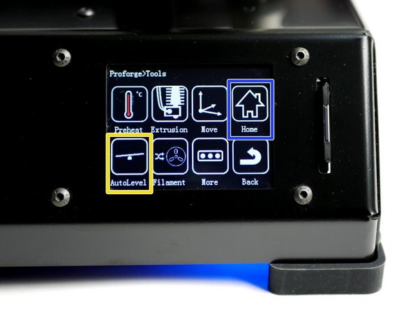
Using the touch screen go to Tools -> Home.
-
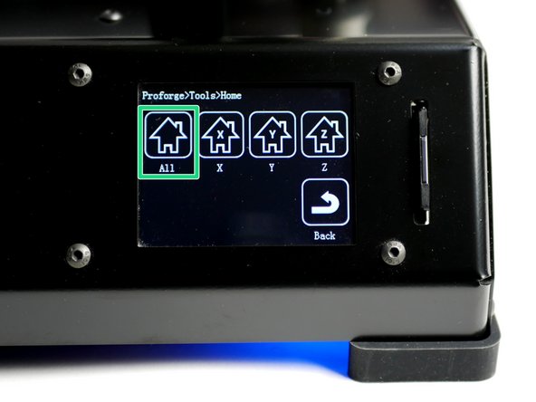
Home X
-
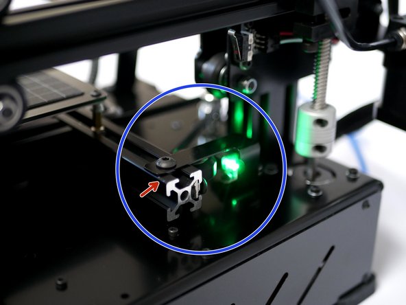
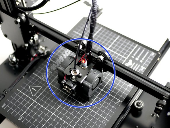
With X homed the nozzle should land above the right edge of the print surface.
-
If you find the nozzle not lining up correctly in the X direction adjust the endstop trigger to achieve better alignment. The distance between the end of the beam and the edge of the metal part should be approximately 6mm.
-
-
-
Home Y
-
The nozzle should land about 1cm from the top edge of the print surface, this is OK.
-
-
-
If you have the Flexplate upgrade make sure it is on the platform before starting.
-
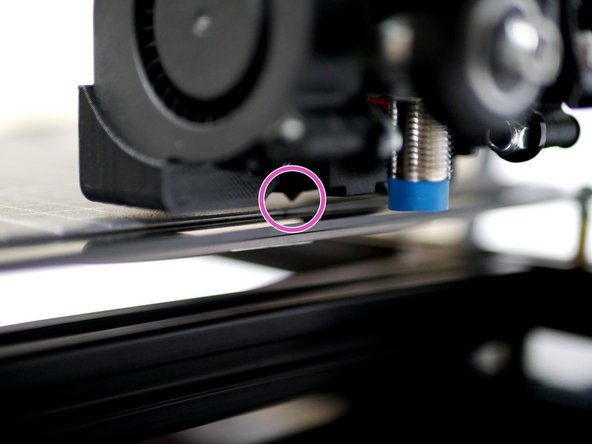
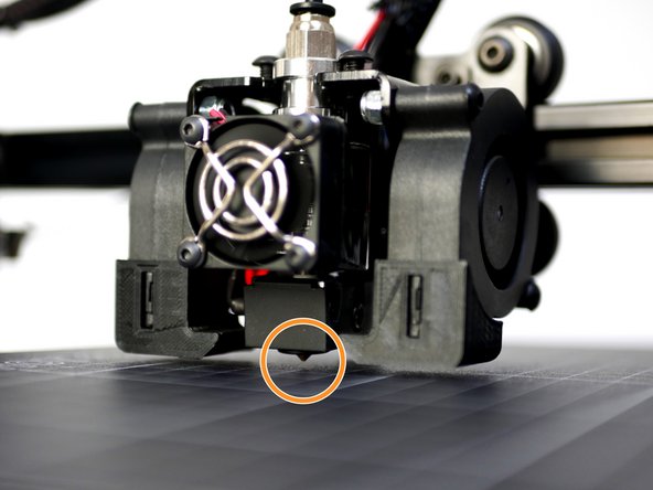
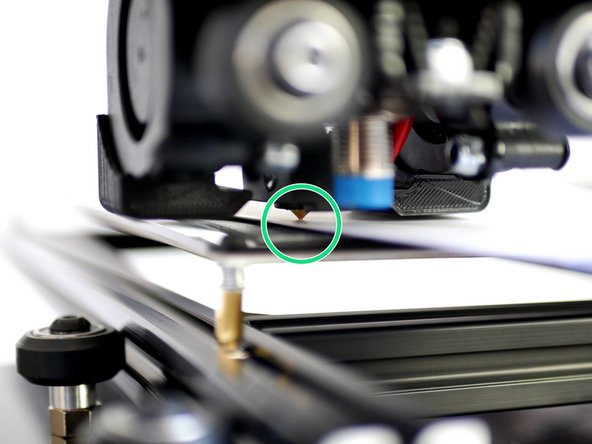
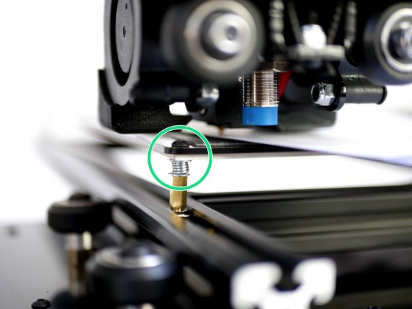
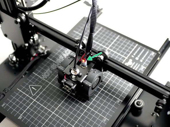
Lower the gantry by hand so that the nozzle comes close to the print surface. Once close enough the red light on the probe should come on.
-
The nozzle tip should always remain above the surface when the probe is triggered. The bottom of the probe should always remain above the tip of the nozzle.
-
Nozzle too close or hits the print surface before the red light on the probe comes on:
-
Lower the probes position on the mount and check again.
-
Red light on probe but nozzle tip is too far away from the print surface:
-
Raise the probes position on the mount and check again.
-
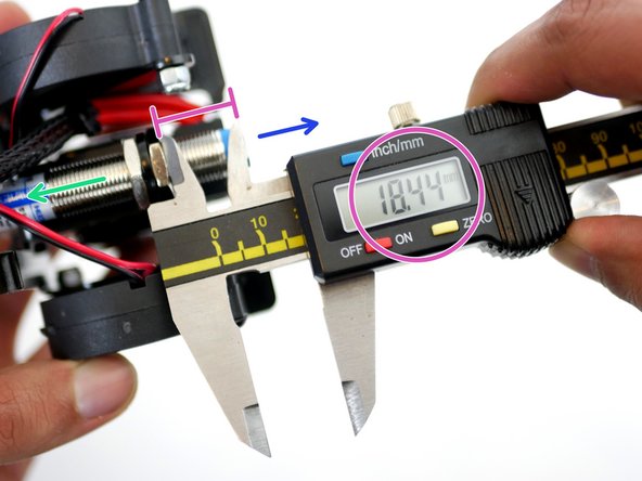
The optimal position of the probe is around 18mm from the bottom of the probe and the bottom of the lower nut as shown in the 3rd image.
-
-
-
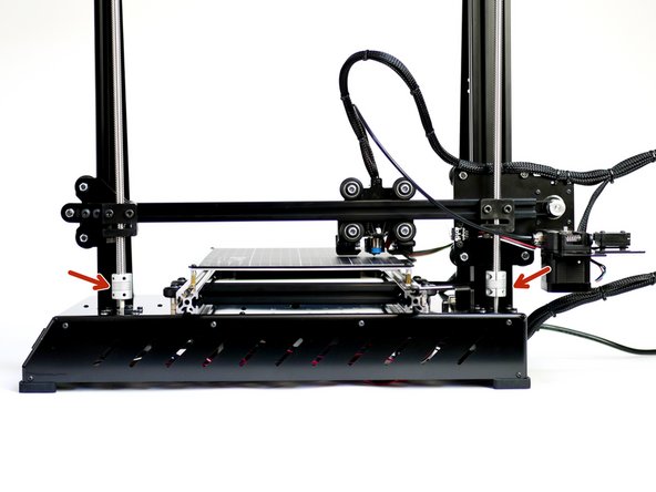
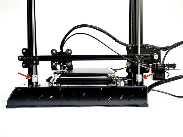
The Proforge 2/2S features automatic bed-levelling but to help get more accurate results we need to first make sure that the bed is physically as level as it can be.
-
Adjust the z-motors so to get the distance between the nozzle and print surface along the y-axis (gantry) equal.
-
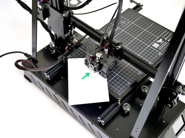
Use a folded piece of paper to feel the gap between the nozzle and print surface.
-
-
-
Next use the springs on the platform to level the print surface in the X-direction (or both the X & Y direction if you're building the Proforge 2).
-
Turn the screw anti-clockwise to raise that corner of the platform.
-
Use a folded piece of paper to feel the gap between the nozzle and print surface.
-
-
-
To check that the probe and bed is set up correctly we are going to Home all of the axes together.
-
Using the touch screen go to tools -> Home -> Home All
-
X & Y will automatically home first. Then the probe should move to the centre of the platform and slowly lower until it's triggered.
-
The gantry will go up at first and then begin lowering - this is normal.
-
Have your finger ready on the power switch to power off in the event of a crash. If you do crash the hotend into the platform re-check your probe postioning - it's likely too far above the nozzle and needs lowering.
-
-
-
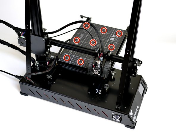
With a successful Z Home go to Tools -> auto-level. Press ONCE.
-
The axes will home again and the sensor will now go around the platform probing 9 points.
-
Again, have your finger ready on the power switch to power off in the event of a crash.
-
Once the Auto-levelling has been completed, re-home all of the axes to return the nozzle to the centre of the platform.
-
-
-
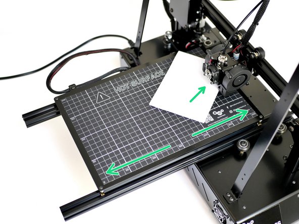
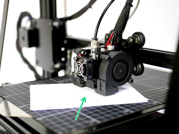
Take the folded piece of paper and place it between the surface and nozzle.
-
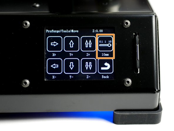
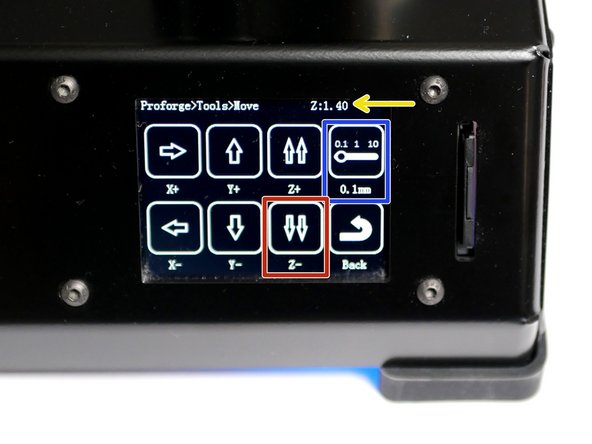
On the touch screen go to Tools -> Move and toggle the distance selector to 0.1mm.
-
Use the touch screen display to lower the nozzle (z-axis) in 0.1mm increments until it begins to grip the paper.
-
Make a note of the Z height displayed on the top right of the touch screen when the paper begins to be gripped. (This value will be 3.00mm to begin with, this is normal.)
-
In this case it ended up being 1.40mm when the paper began to be gripped, but this value will be different for everyone.
-
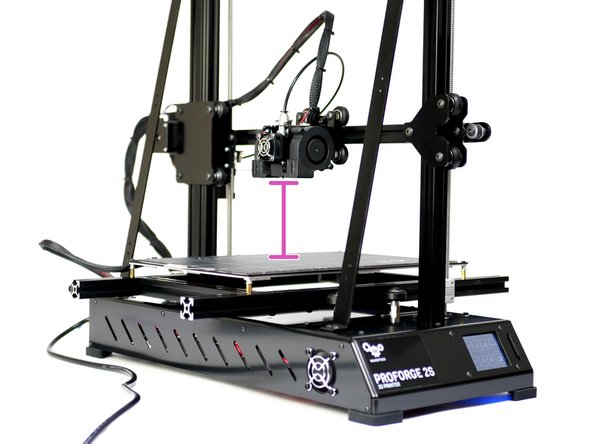
When done raise the nozzle up about 80mm.
-
-
-
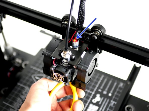
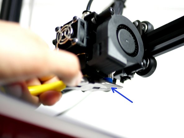
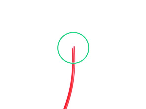
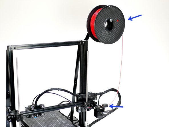
Take the included sample of PLA filament out of its packaging.
-
Use the included pliers to cut a sharp end.
-
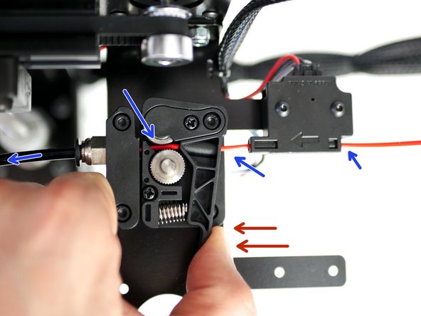
Place the spool of filament onto the spool holder and feed the filament through the filament sensor.
-
Press down the Idler arm and push the filament in through the feeder and through the PTFE tubing until it reaches the Hotend and you can't push it in any further.
-
-
-
Before powering up the Hotend make sure that the black PTFE tubing is pushed all the way down the Hotend, it should go into the Hotend by 6CM. Double check, as running filament through the hotend with the PTFE tube not all the way down will ruin the Hotend.
-
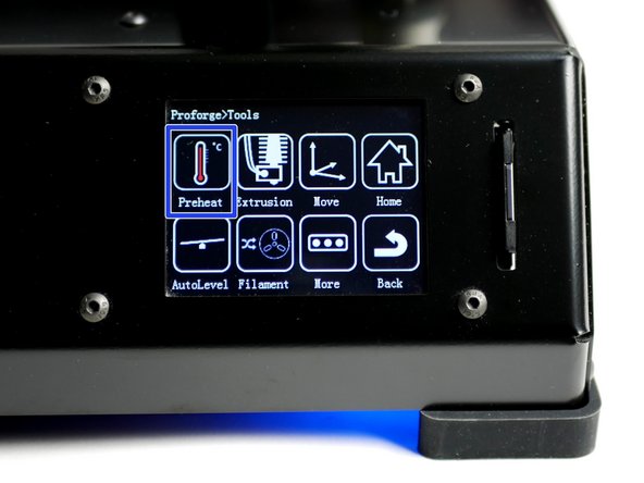
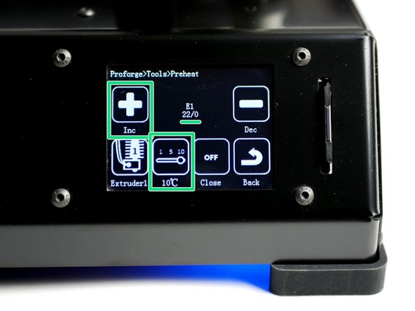
On the touch screen go to Tools -> Preheat
-
Heat the Hotend up to 200C.
-
Wait for the Hotend to heat up.
-
Caution - the Hotend will cause burns if touched while hot!
-
-
-
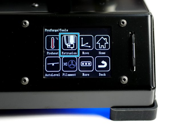
With the Hotend up to temp and the filament loaded, go to Tools -> Extrusion.
-
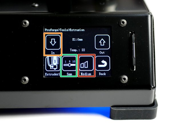
This is the length of filament that will be fed, each time you tap the down arrow.
-
This is the speed setting.
-
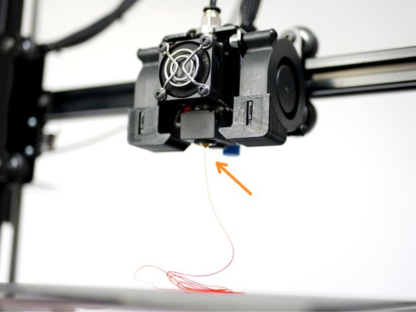
You should have a smooth and continuous flow of plastic coming out of the Hotend nozzle.
-
The extruded plastic will be hot!
-
NOTE: When powering down from a hot Hotend, power the hotend down first and let it cool to at least 100C before completely powering off - as this prevents the heat from rising up the Hotend with the absence of the fan cooling it.
-
If you are not getting any filament extruded check the extruder motor is turning in the correct direction (anti-clockwise) to feed the filament. See next step if your extruder is turning in the wrong direction.
-
-
-
If an extruder from the previous step moves in the wrong direction power off your printer and disconnect the touchscreen.
-
In the Aruino IDE go to the "configuration.h" tab.
-
Scroll down to line 863. (Go to File -> Preferences and check "Display line numbers")
-
#define INVERT_E0_DIR false
-
Replace false with true to change the motors direction.
-
Re-upload the firmware.
-
Once uploaded, connect back the touch screen and power up the printer from the mains again.
-
Continue from previous step.
-
-
-
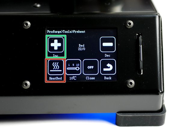
Go to Tools -> Preheat
-
Press the extruder icon to toggle to the bed.
-
Power on the bed by setting its temperature to 60C - typical for PLA printing.
-
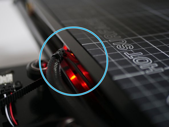
A red LED should shine on the back of the heated bed and it should begin to heat up.
-
Avoid touching the bed whilst hot!
-


Cancel: I did not complete this guide.
13 other people completed this guide.

3 Comments
Yeah i double checked that it was plugged in the right spot, and the power was on otherwise i could not controll the motors and everything else, i will try to reupload my touch screen firmware, maybe theres a problem cos i only got one extruder in the firmware even tho i took the 2s
Raphael Lehner - Resolved on Release Reply
Hey, first i have to say those are really nice guides, secondly i have got a problem with my printer fans (step 15) because they are working when i clip them to 12V but arent doing anything when I turn them on via the Settings as it is supposed to be
Raphael Lehner - Resolved on Release Reply
Have you checked that you have connected them to the correct position on the board. When trying to power up the print fans from the touch screen you need to make sure that you are connected and powered from the mains too and not just the USB port.