
-
-
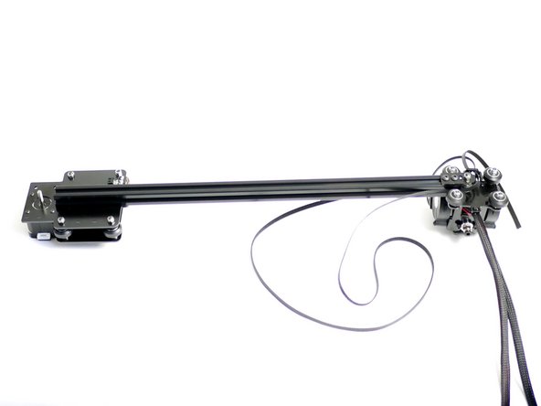
Take the remaining 1.4M of GT2 Timing Belt and feed it into the Y-Carriage as shown in the second image.
-
Make sure the loop has no turns in it and the teeth are facing inwards through out.
-
Fix an M4 x 12mm bolt with M4 nyloc nut as shown.
-
Do not tighten all the way as we'll be needing to pull the belt tight later.
-
-
-
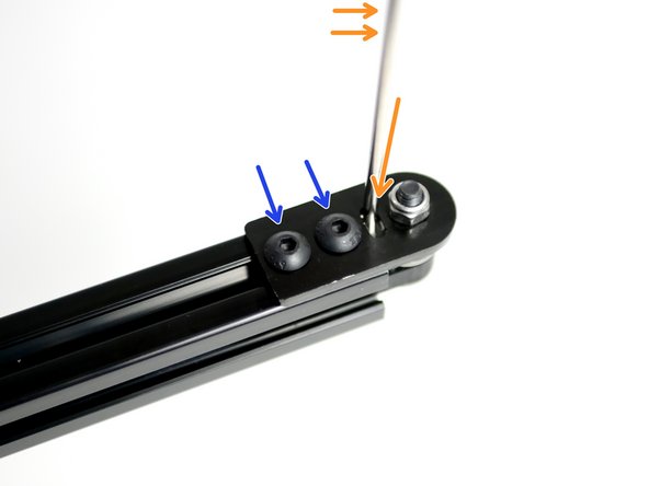
Fasten two M5 x 8mm and M5 T-Nuts onto the Y-Idler.
-
Do not fasten all the way down.
-
Later versions of the kit do not include in this specific Idler part, instead you should use one of the extrusion brackets instead.
-
-
-
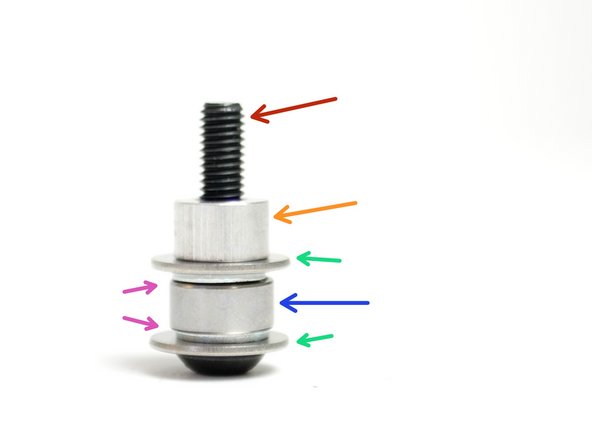
Assemble the Y-Idler:
-
M5 x 25mm Bolt
-
M5 Spacer
-
M5 15mm Washer
-
M5 Washer
-
Bearing - 685ZZ
-
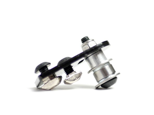
Fix the Idler Assembly onto the Y-Idler bracket with an M5 Nyloc Nut - Match the orientation as in the second photo.
-
Make sure that after tightening the bearing can still spin.
The 685ZZ bearing is with the other mechanical parts in box B.
Makertech 3D - Resolved on Release Reply
Bearing - 685ZZ ??
As this part is not inside the “06 Gantry” bag it should be pointed out where it can be found and/or a photo of it NOT assembled with the other parts should be shown!
Fabian Groß - Resolved on Release Reply
-
-
-
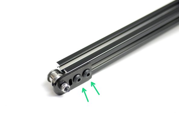
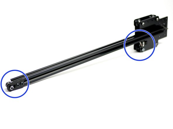
Fix the Y-Idler assembly onto the end of the gantry beam.
-
The Y-Idler assembly should be fixed onto the same side as the endstop.
-
Make sure that the 15mm washers are pressing against the end of the beam.
-
-
-
Begin by laying down the gantry and tool carriage assembly like shown in the first image.
-
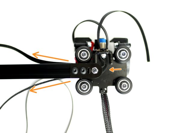
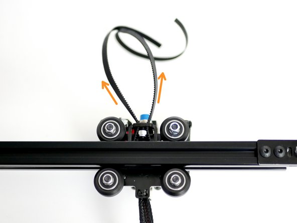
Bring the rollers up to the gantry beam making sure to trap the belt loop in the grooves of the beam with teeth facing inwards.
-
-
-
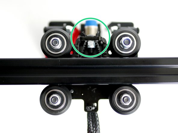
Push the Tool Carriage onto the gantry beam.
-
As you slide the tool carriage onto the gantry beam the belt should loop itself around the Idler pulley bearing.
-
Make sure that the belt is tucked into the grooves between the rollers and gantry beam.
-
You may need to adjust the eccentric spacers on the carriage if it's not sliding on.
-
-
-
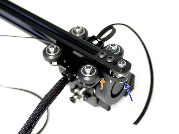
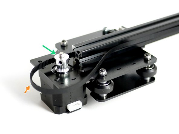
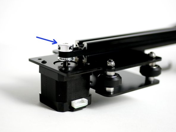
Drop onto the other side of the gantry a pulley onto the Y-Motor shaft. Match the orientation of the pulley in the image.
-
Loop the other end of the belt onto the pulley.
-
Make sure that the belt runs through the grooves of the gantry beam.
-
-
-
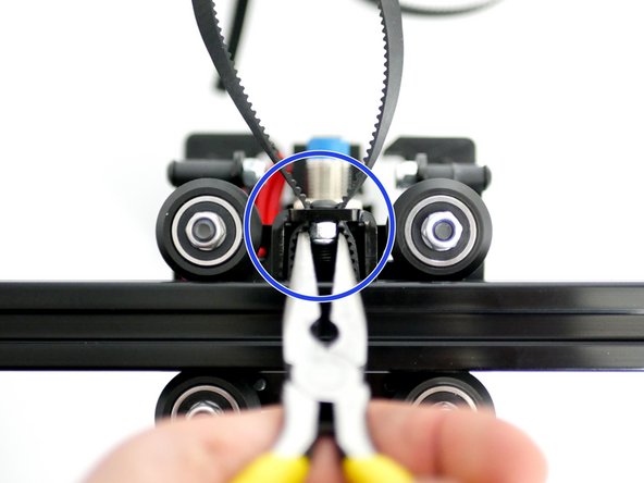
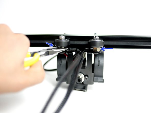
Pull the loose ends of the belt tight.
-
The teeth of the belt should catch on the bolts head holding the tension temporarily.
-
If you find it slipping way too much, tighten the M4 bolt a little more and pull the belt again, pulling the belt with the pliers will allow you to get a higher tension.
-
Use a pair of pliers to hold the Nyloc nut as shown in the second image and tighten down the bolt.
-
-
-
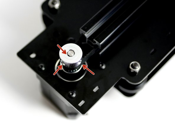
Slide the pulley up to the end of the motors shaft.
-
Secure the pulley by tightening the set screws
-
Make sure that one of the set screws is being tightened against the flat of the motor shaft.
-
-
-
Postpone this until Stage 7 Step 18 - Y-Idler install.
-
Loosen the bolts holding the the Y-Idler assmebly to the gantry beam.
-
Use a screw driver or allen key as a lever to pull the idler away from the end of the beam.
-
Hold the tension and tighten down the M5 bolts.
-
-
-
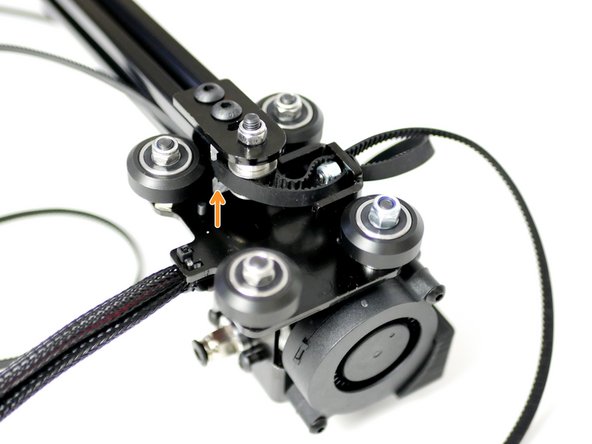
Rotate the Eccentric Spacers with a pair of pliers.
-
Tighten until there is no wobble on the Carriage.
-
-
-
Proforge 2S: Postpone this step until after Stage 7 Step 18 - Y-Idler install.
-
Proforge 2: Do this step now. Cut away the excess belt from the carriage.
Don’t cut much, leave some at least until step Stage 07 - Z - Motion + Frame
Miracle Max - Resolved on Release Reply
-
-
-
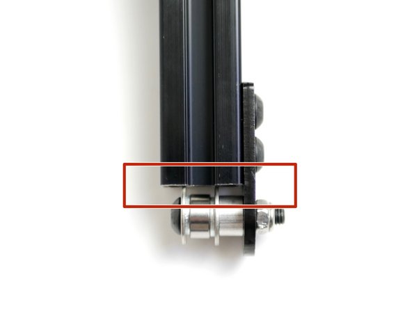
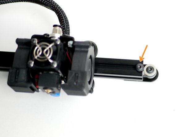
Fix an M5 x 8mm bolt with a T-Nut onto the end of the gantry beam to act a stopper for the Tool Carriage to prevent it from accidentally rolling off.
-
-
-
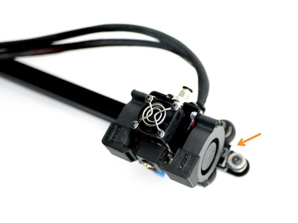
Push the tool carriage out up to the stopper.
-
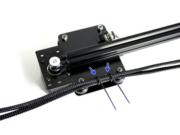
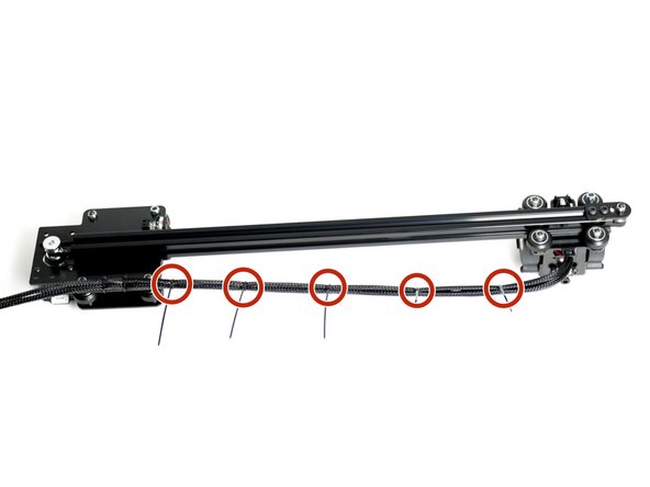
Push two cable ties into the Z-Axis Bracket holes as shown and secure the cables to it.
-
Wrap cable ties around both of the cables from the Z-Axis bracket to the tool carriage.
-
Trim away any excess form the cable ties.
For the dual switching extruder this is presumably done later, as the nozzles haven’t yet been attached?
John Gardner - Resolved on Release Reply
-


Cancel: I did not complete this guide.
22 other people completed this guide.
