
Tools
Parts
No parts specified.
-
-
Download the following:
-
-
The download also includes other files related to the Axis. You can view the repo on Github here.
-
-
-
-
-
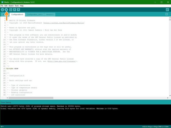
Open Marlin.ino in the Arduino IDE
-
Marlin -> Marlin.ino
-
Go to File -> Preferences and check "Display line numbers"
-
-
-
If you have installed the heated bed upgrade you will need to activate it in Marlin to use it.
-
In Configuration.h scroll to line 417 and set the TEMP_SENSOR_BED value to "1".
-
-
-
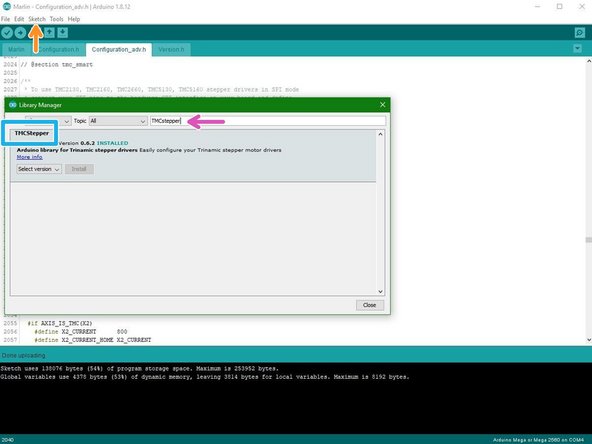
Skip this step if you don't have any TMC2208 drivers installed.
-
In the Arduino IDE go to Sketch -> Include Library -> Manage Libraries...
-
Search for TMCStepper and install the latest version.
-
-
-
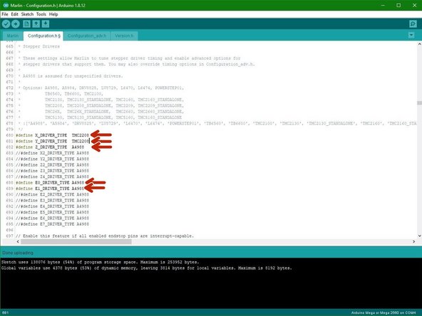
Skip this step if you don't have any TMC2208 drivers installed.
-
Scroll down to the Stepper Drivers section of the Configuration.h file.
-
Replace A4988 with TMC2208 depending on where you have the drivers installed on the board.
-
The example shows TMC2208 drivers installed on just the X and Y axes.
-
-
-
When running the TMC2208 drivers you will also need to invert the motor directions for the axes that you have them installed on:
-
Scroll to line 1067 (File -> Preferences -> display line numbers) and set as shown if that axis has a TMC2208 driver installed:
-
INVERT_X_DIR true
-
INVERT_Y_DIR true
-
INVERT_Z_DIR false
-
INVERT_E0_DIR true
-
INVERT_E1_DIR true
-
-
-
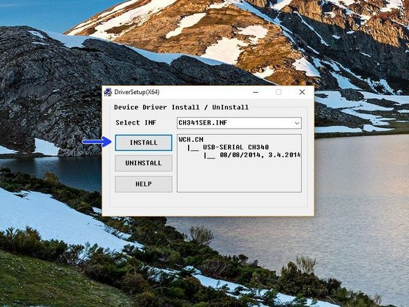
In the USB driver folder on PC double click on the CH341SER Driver - PC.EXE file. On MAC see the Readme.pdf file in the Mac folder.
-
You may need to right click, "run as admin" to open.
-
Once open, click INSTALL.
-
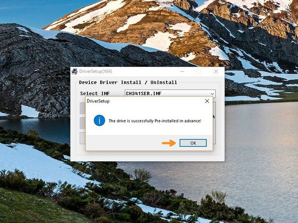
Once done, you should get a success message, click OK and close the programme.
-
-
-
Before continuing, move all of the axes to safe positions:
-
X and Y to approx the centre.
-
And Z raised approx 100mm.
-
-
-
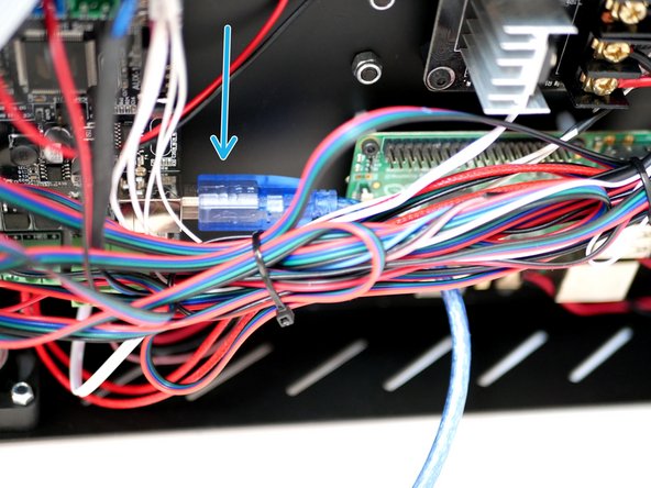
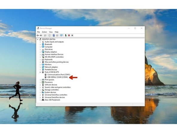
Connect the AXIS to your PC via the usb cable.
-
On windows you can open device manager by right clicking the windows icon. The Printer should show up as CH340, note the COM port number. In this case COM4.
-
We recommend using USB2.0 ports as 3.0/SS ports have been known to cause problems.
-
-
-
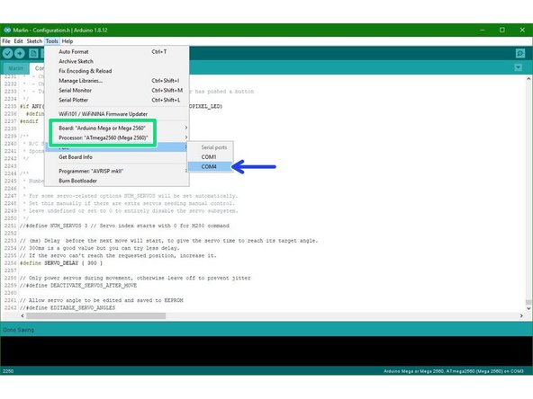
Go to tools and set the port to the COM number that is for the AXIS.
-
Make sure that the board and processor are both set to Mega 2560.
-
Finally upload the firmware to the AXIS.
-
-
-
Once the firmware has completed uploading, connect the AXIS to the mains.
-
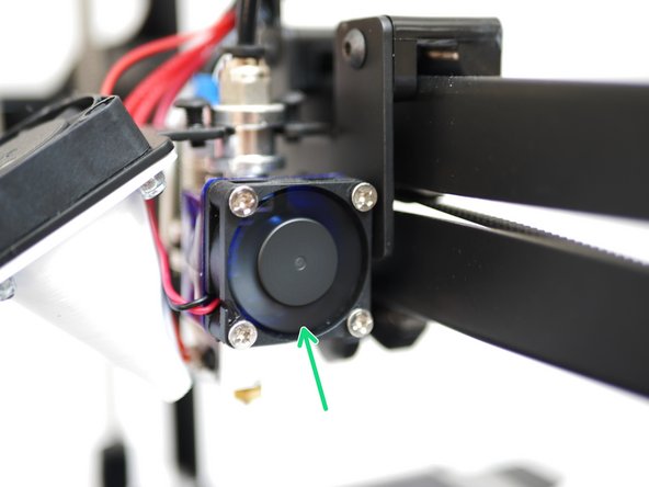
When powered up, check that the electronics fan and the hotend fan are both spinning.
-
-
-
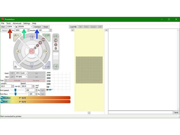
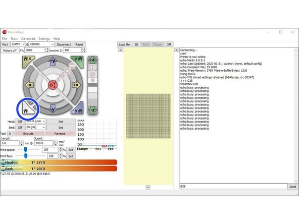
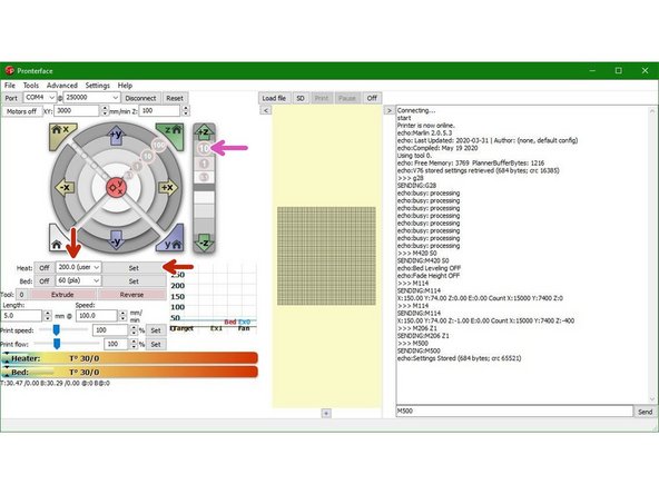
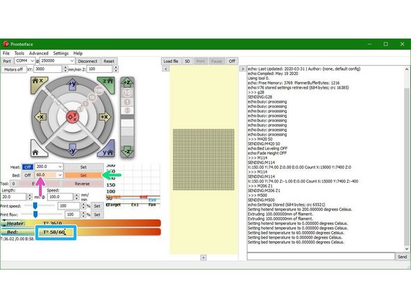
Open the Pronterface software.
-
Set the port to the same COM number.
-
Set the baudrate to 250000.
-
Finally, hit connect.
-
If you get an EEPROM error send M502 followed by M500 to reset and save the EEPROM.
-
-
-
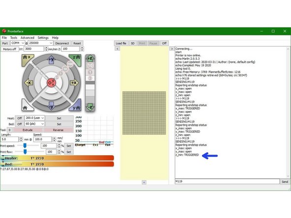
Send an M119 command to check the status of the endstops.
-
They should all report back "open".
-
Manually push down the X-Axis endstop, and whilst keeping it pushed, send the M119 command again. It should report back as "triggered".
-
Repeat this for the Y-axis endstop also.
-
-
-
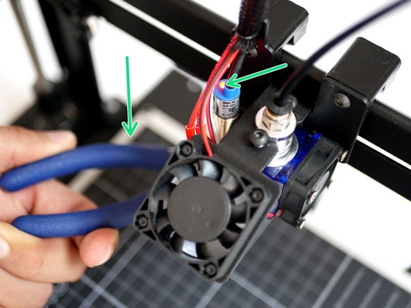
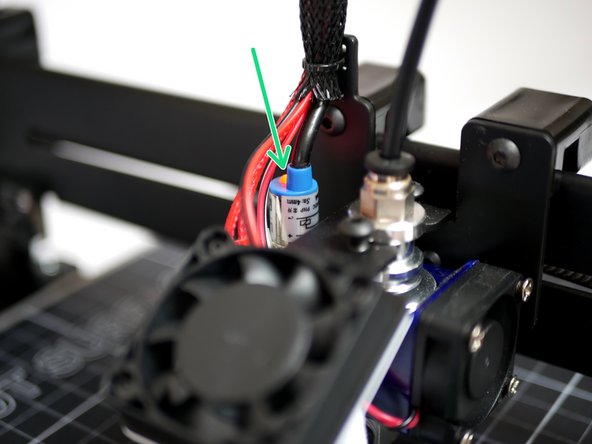
Whilst holding a metal object under the probe (a red light should shine) send the M119 command.
-
Pronterface should return: z_min: TRIGGERED.
-
When the metal object is removed, (and the red light now not shining) send the M119 command again. This time it should return as open.
-
-
-
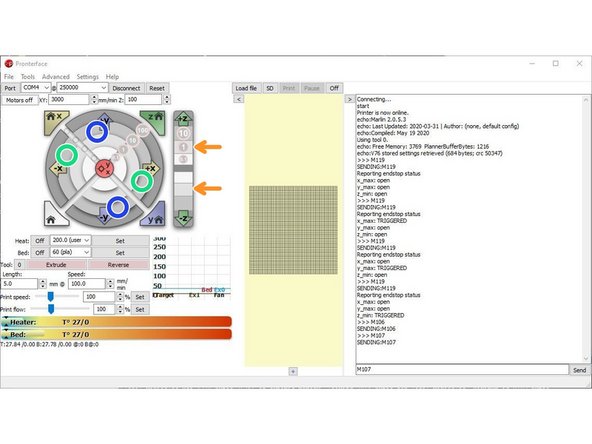
Send an M106 command to power on the part cooling fan.
-
Send an M107 command to turn it off.
-
-
-
Use the control interface on pronterface to move the printer axes. Make sure to only move 10mm at a time. Because we haven't homed yet there is a potential for a crash so movements need to be small, we are only confirming movement in the correct direction here.
-
X-Axis: Pressing the left arrow will move the bed to the right, and vice versa.
-
This is correct as the nozzle position has moved in a negative direction relative to the platform.
-
Y-Axis: Pressing the down arrow will move the Hotend towards the front of the printer and vice versa.
-
Z-Axis: Pressing the up arrow on the Z-axis will move the gantry up and vice versa.
-
If an axis moves in the opposite direction see the next step.
-
-
-
If an axis from the previous step moves in the wrong direction power off your printer.
-
In the aruino IDE go to the "configuration.h" tab.
-
Scroll down to lines 1066-1069. (Go to File -> Preferences and check "Display line numbers")
-
#define INVERT_X_DIR true
-
Change false to true to switch the motors direction depending on the problem axis (X, Y or Z).
-
Re-upload the firmware.
-
Continue from the previous step.
-
-
-
Click in the following order, allow each command to complete before moving to the next:
-
Home X - The platform will move all the way to the left until the end-stop on the base is triggered.
-
Home Y - The hotend will move towards the z-pillar until the eccentric guide triggers the end-stop on the gantry.
-
Lower the Z axis - Lower the gantry incrementally to check the that the nozzle is aligned with the top right corner of the print surface, this is your (300,200) co-ordinate.
-
The hotend nozzle should be above the top right corner of the print surface.
-
-
-
If you have the Flexplate upgrade make sure it is on the platform before starting.
-
Click "motors off" in Pronterface. Manually move the tool carriage so that the probe is hovering over the centre of the platform.
-
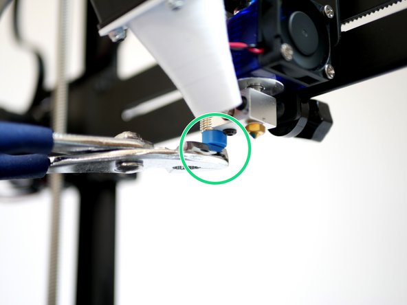
Lower the gantry by hand so that the nozzle comes close to the print surface. Once close enough the red light on the probe should come on before the nozzle hits the print surface.
-
Ideally, when the probe is triggered (as soon as its light shines) the tip of the nozzle should be no more than 1mm above the print surface.
-
Nozzle hits the print surface before the red light on the probe comes on:
-
Lower the probes position on the mount and check again.
-
Red light on probe but nozzle tip is too far away from the print surface:
-
Raise the probes position on the mount and check again.
-
-
-
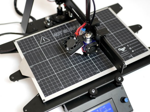
Home all of the axes by clicking here or sending G28.
-
Before sending the command be ready to unplug the power from the printer in case of a crash.
-
If you do crash, disconnect/reconnect from pronterface before powering back on again. Check your probe setup is triggering correctly.
-
-
-
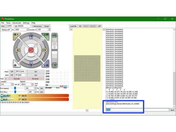
After successfully homing with G28 run the G29 autolevel command.
-
20 points on the print surface will be probed and a mesh of the surface will be created.
-
Once a mesh is generated send M500 to save it to the printers memory.
-
-
-
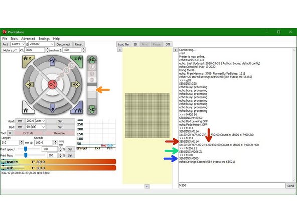
Send G28 to home all axes.
-
Send "M420 S0" to turn off the auto-levelling.
-
Send M114 to report the nozzle position, the Z-axis should be at 0
-
-
-
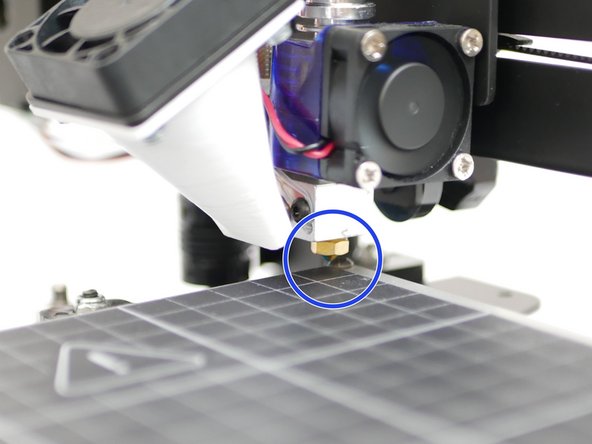
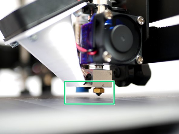
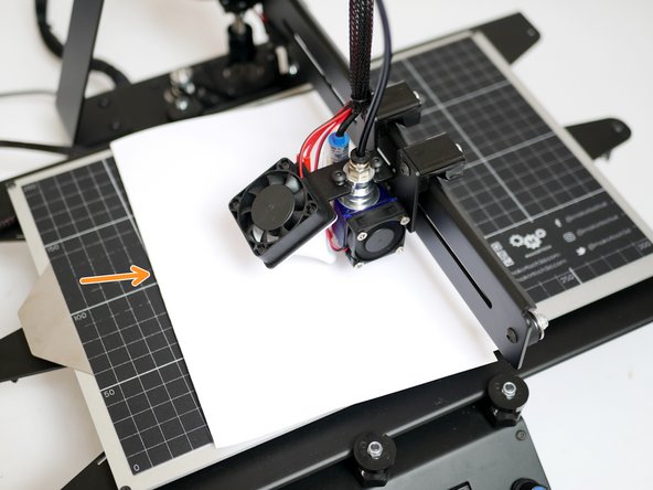
Place a folded piece of paper between the nozzle and print surface. Lower the Z axis in 0.1mm increments until the nozzle grips onto the paper.
-
Send the M114 command again to report the Z-axis position.
-
The amount that you lowered the z axis by is your Z-offset.
-
In this example case M114 reported the new z-position to be -1 when lowered to grip the paper. There for the Z-offset is 1mm.
-
Enter M206 Z(value)
-
As in this example case the Z-offset was found to be 1, we enter "M206 Z1".
-
Send an M500 command to save it to the printers memory.
-
-
-
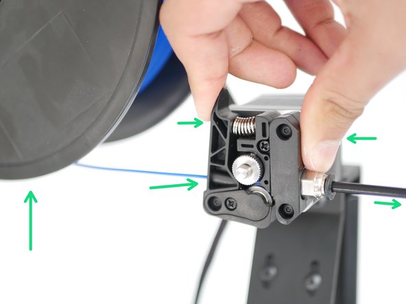
Take your PLA filament and cut a sharp end.
-
Place the spool onto the holder and feed the filament in through the extruder like shown, until it hits the bottom of the hotend.
-
-
-
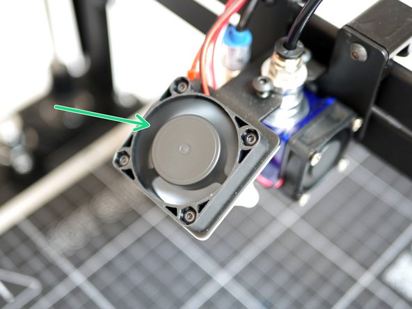
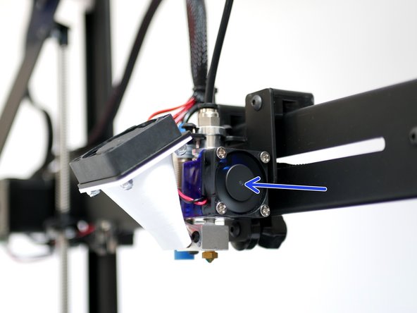
Make sure that the 30mm fan is spinning, this fan should always be one, powering your hotend without this fan on will cause damage.
-
Raise the gantry up by between 60-80mm
-
Set the hotend to 200 degrees and press set to begin heating.
-
Wait for the hotend to heat up.
-
Caution - the Hotend will cause burns if touched while hot!
-
-
-
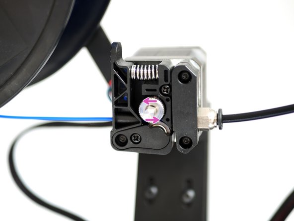
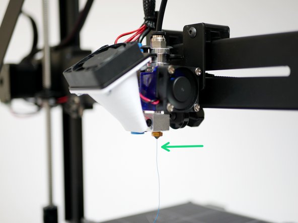
Once the hotend has reached 200 degrees celcius, you can begin extruding.
-
Press extrude to extrude the filament.
-
Check the motion of the drive gear, it should turn anti-clockwise in order to feed filament into the hotend.
-
You should have a nice, straight stream of filament flowing from the nozzle.
-
NOTE: When powering down from a hot Hotend, power the hotend down first and let it cool to at least 100C before completely powering off the printer - as this prevents the heat from rising up the Hotend with the absence of the fan cooling it.
-
In case the extruder turns the other way, clockwise, you will need to reverse the motors direction in the firmware (INVERT_E0_DIR), see step 15 for doing so.
-
-
-
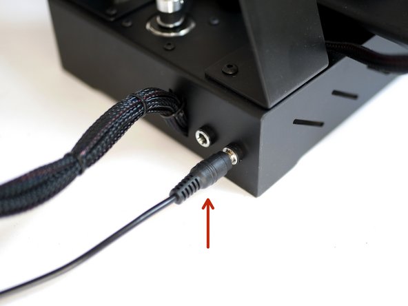
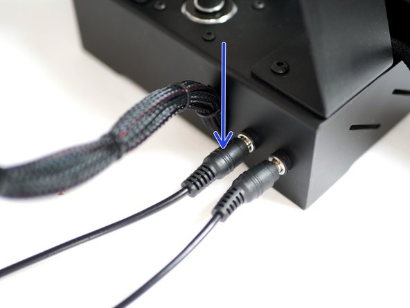
First make sure that the beds power supply is plugged in and switched on at the mains.
-
Set the bed temperature to 60 degrees Celsius.
-
Press set to power on the bed.
-
A red LED on the back of the heated bed should shine to indicate heating.
-
Let the bed get up to 60 degrees before shutting it off.
-
Caution, avoid touching the bed when hot.
-


Cancel: I did not complete this guide.
11 other people completed this guide.
