-
-
Build the touch screen and case assembly as shown.
-
M3 x 8mm Bolt
-
Metal Mount
-
3D Printed Case
-
HDMI 5 Touch Screen Display
-
-
-
Build the swivelling mechanism as shown:
-
M3 x 8mm Bolt
-
M3 Washer
-
Connecting Bracket
-
Mounting Bracket
-
M3 Nyloc Nut
-
-
-
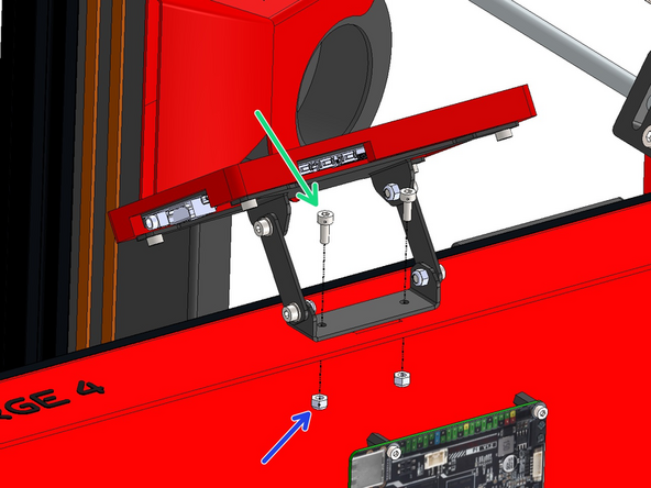
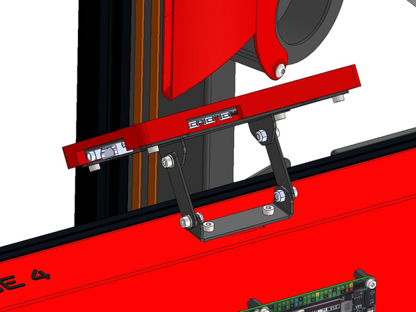
Mount the display onto the base as shown:
-
M3 x 8mm Bolt
-
M3 Nyloc Nut
-
-
-
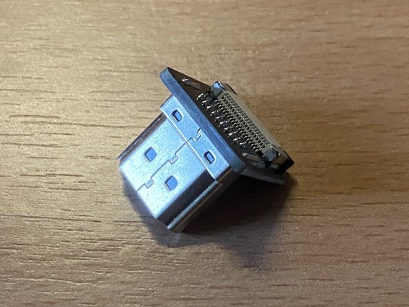
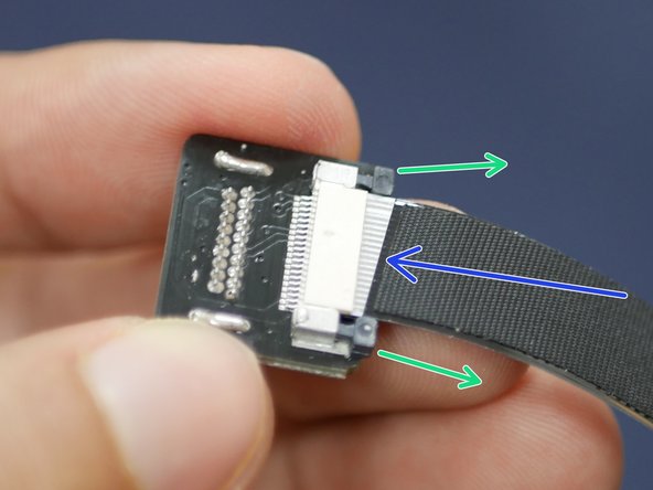
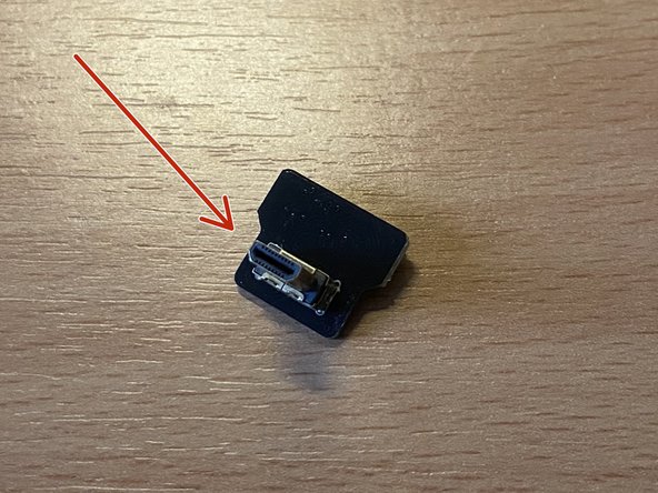
Connect one of the ribbon cables to the HDMI connector.
-
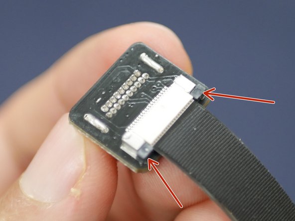
Do this by carefully pulling the black tabs here out.
-
Next push the ribbon cable in, with the pin side facing up.
-
Push the black tabs back in to hold the ribbon cable in place. It's important to make sure the cable is seated straight and with none of the pins showing.
Take care you've picked up the USB C plug – the Micro HDMI looks v. similar.
Mark Wheadon - Resolved on Release Reply
-
-
-
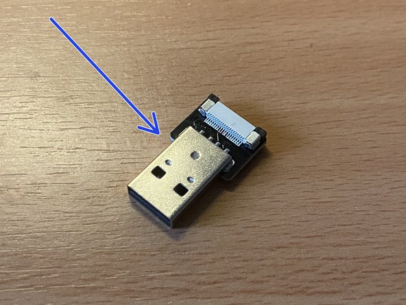
Connect the other ribbon cable to the USB C connector in the same manner.
-
-
-
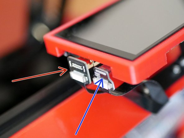
Connect the cables to the display ports as shown.
-
HDMI
-
USB C
-
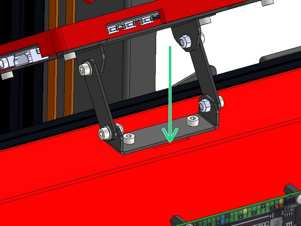
Feed the free ends of the ribbon cable in through the slit on the base.
-
-
-
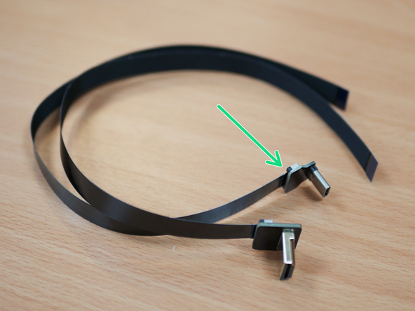
Fix to the other side of the HDMI connectors ribbon cable the Micro HDMI connector.
-
Fix to the other side of the USB C connectors ribbon cable the USB A connector.
-
Connecting these the wrong way round will result in damage to the display and/or Pi board.
-
-
-
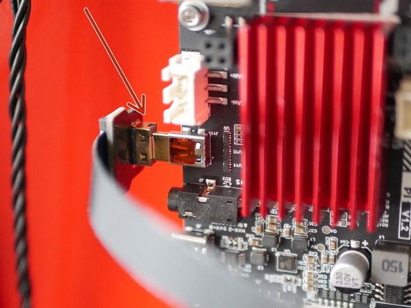
Plug the micro HDMI connector to the port on the side of the BTT Pi.
-
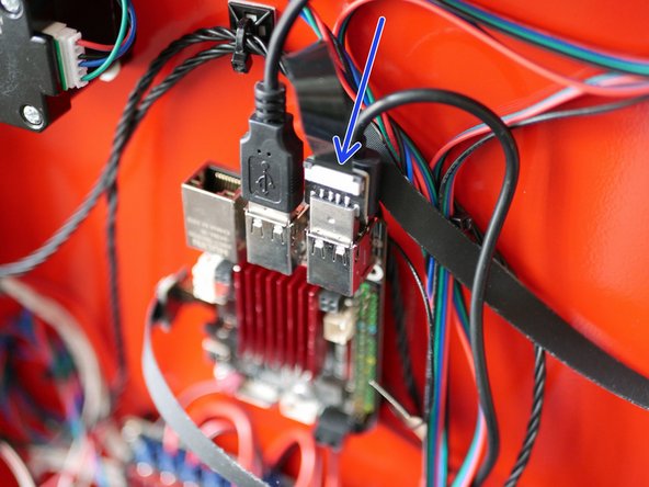
Plug the USB connector to a USB port on the BTT Pi (or USB hub if building the 4.2)
Every USB except the print heads has been labeled "plug in to Pi", but there's more than 4. Which ones should be plugged in to the external hub? I don't want something like the camera to saturate the hub and cause comms problems with the Orbiters.
For this version of the touch screen we recommend connecting it or the Eddy probe to the hub.
-
-
-
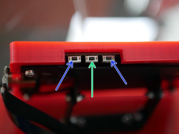
There are three buttons underneath the display on the edge.
-
The centre one controls the orientation of the screen.
-
The two either side control the displays brightness. If your display is not lighting up it may be that the brightness is set all the way down.
-
Cancel: I did not complete this guide.
10 other people completed this guide.



Tip: the screw posts on the screen are not anodized orange. You'll need to remove those kapton stickers before the screws will go in...
Darren - Resolved on Release Reply
...and you didn't pack me a 3D printed case. I'll print one – assuming I can find the STL. It won't be colour matched to the rest of the printer though, which is a shame :(
Mark Wheadon - Resolved on Release Reply