
-
-
Before starting a stage we recommend sorting the fasteners from the fastener packs first for a quicker work flow.
-
-
-
Attach the side panels to the base with twelve M3 x 8mm bolts and twelve M3 Nyloc Nuts.
-
The left panel should have the fan mounting holes.
-
Drop all of the bolts for the panel in first to get the proper alignment.
-
M3 x 8mm Bolt
-
M3 Nyloc Nut
-
A pair of pliers will be needed to hold the nut as you tighten down the bolt.
-
-
-
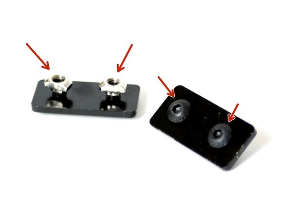
Prepare two steel extrusion brackets with two M5 x 8mm bolts and two M5 T-Nuts.
-
Loosely attach the M5 T-Nuts.
-
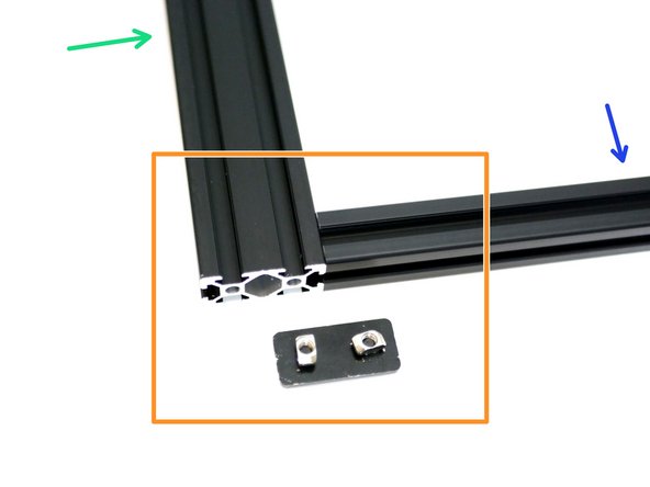
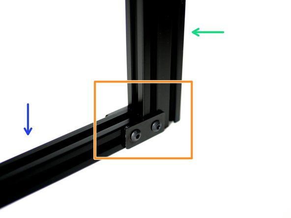
Use the steel extrusion brackets to fix together the 2040 x 500mm and 2020 x 360mm beams.
-
Match the image exactly.
-
2040 x 500mm Beam
-
2020 x 360mm Beam
-
Make sure there are no gaps between the two beams and that the 2040 beam is not over hanging.
-
-
-
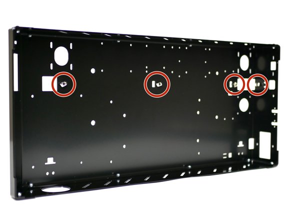
Loosely attach to the base four M5 x 8mm bolts with M5 T-Nuts.
-
-
-
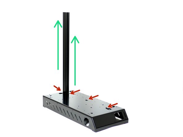
Slide the Support Beam Assembly in through the rectangle hole from the underneath of the Base.
-
The wider 2040 Beam should be pointing upwards.
-
Secure the support beam assembly to the base by tightening down the four M5 x 8mm bolts.
-
Use the rectangle holes to check that all of the T-Nuts have correctly attached to the extrusion beams. Sometime you may need to use the end of an allen key to force them to turn.
-
-
-
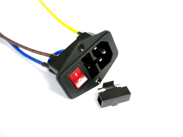
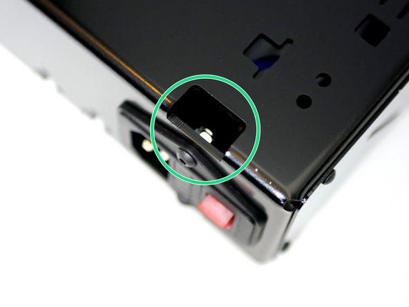
Check that IEC Switch has a fuse by popping open the compartment with a flat head screw driver.
-
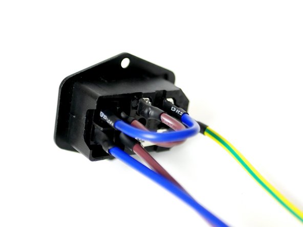
Check that the IEC Switch cables are all properly connected and insulated as shown in the image.
-
-
-
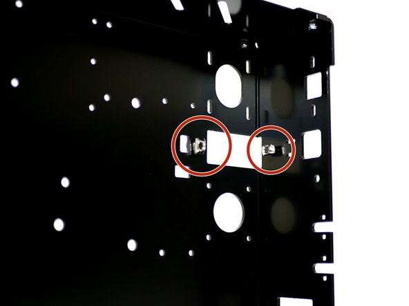
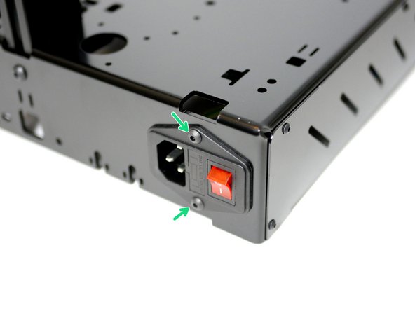
Fix the Switch to the Base with two M4 x 10mm bolts and two M4 Nyloc Nuts.
-
Make sure the red switch faces towards to side panel.
-
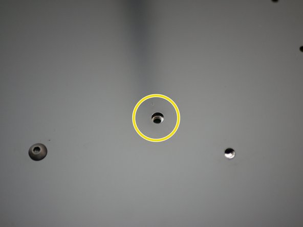
Use the hole in the top of the base to gain access to the top M4 Nut to hold with the pliers.
-
-
-
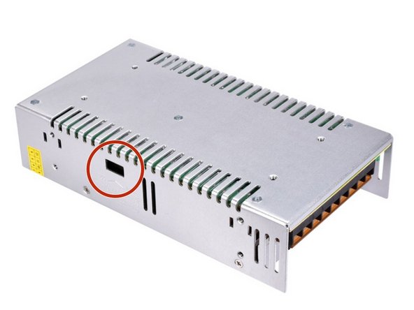
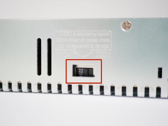
Check that your power supply is set to match your mains voltage by flipping the switch on the side of the unit with a flat head screw driver.
-
INCORRECTLY SETTING THIS WILL DAMAGE THE POWER SUPPLY!
-
-
-
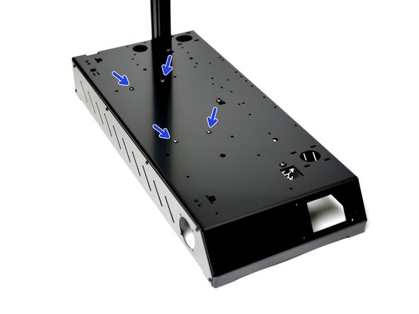
Align the 4mm holes on the back of the power supply with the four 4mm holes on the base.
-
Fix the power supply to the base with four M4 x 6mm bolts.
-
Make sure the screw terminals on the power supply are facing towards the switch.
-
-
-
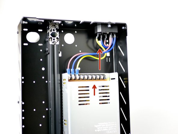
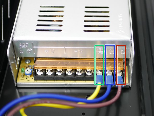
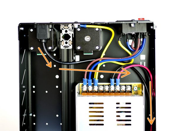
Connect the cables from the IEC Switch to the power supply.
-
Yellow/Green = Earth
-
Blue = Neutral (Negative)
-
Brown = Live (Positive)
-
Match the symbols on the power supply to the cables.
-
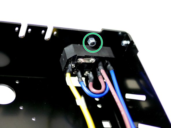
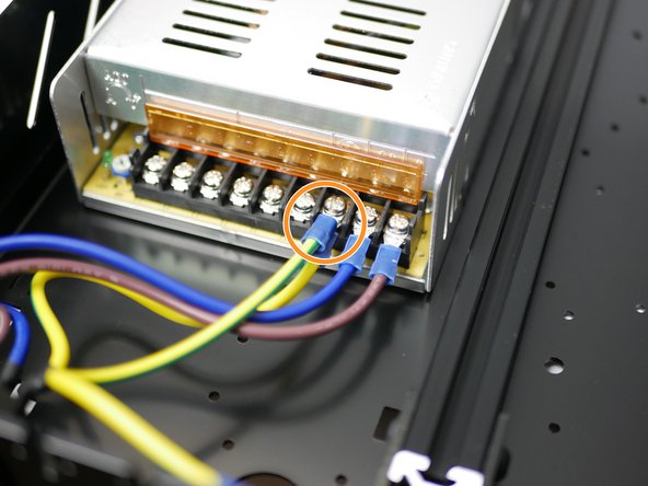
Also connect to the Earth terminal the frame earthing cable.
-
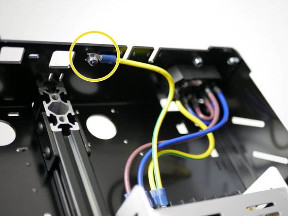
Connect the other end of the cable directly to the frame with an M4 x 10mm bolt and M4 Nyloc Nut.
-
-
-
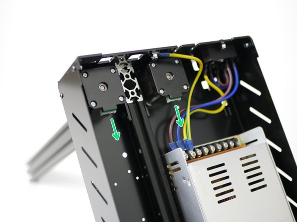
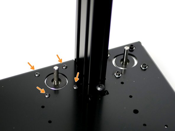
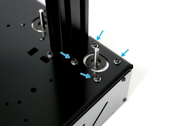
Install two NEMA 17 motors to the Base; orientate the cable ports towards the front of the base.
-
Fix the motor on the left of the 2040 beam with four M3 x 6mm button head bolts.
-
Fix the motor on the right of the 2040 beam with four M3 x 6mm cap head bolts and four M3 washers.
-
-
-
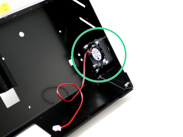
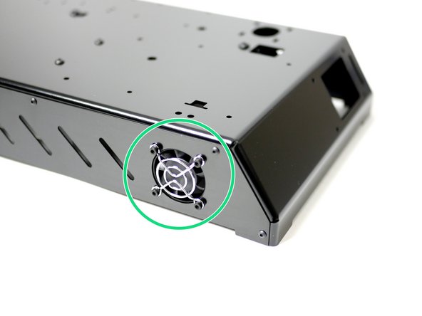
Attach the 40mm electronics fan and fan guard to the side panel with four M3 x 18mm bolts and four M3 nyloc nuts.
-
Orient the fan so that the sticker side faces inwards and the cable points to the roof of the base.
-
-
-
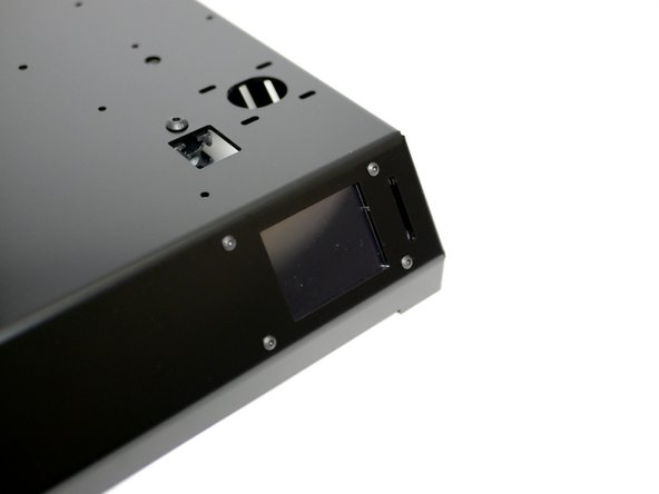
Prepare four M3 x 14mm bolts and four M3 x 5mm spacers onto the touch screens mounting holes.
-
Fix the touch screen onto the base with four M3 nyloc nuts.
-
Ensure you use four (4) M3 x 5mm spacers (Other fasteners bag) or you may risk damaging the screen. Do not over tighten.
-
-
-
Before handling the board ground yourself by touching a large metal object. Also avoid placing the board on carpet or anything that may cause a static charge.
-
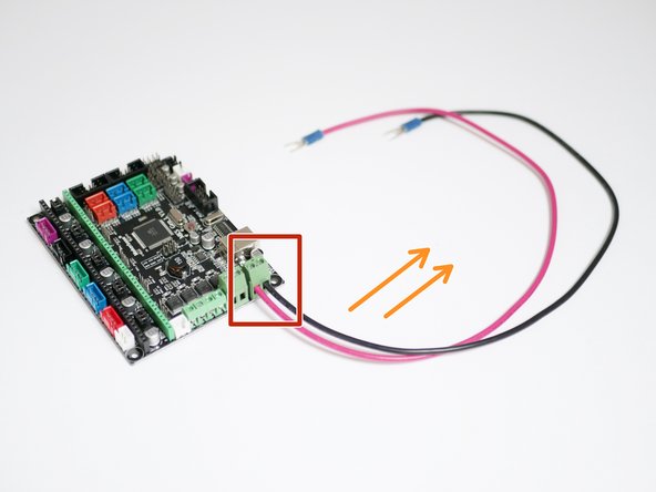
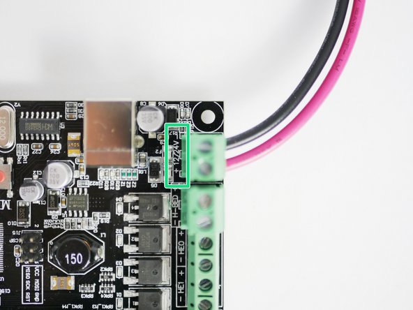
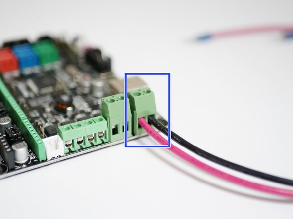
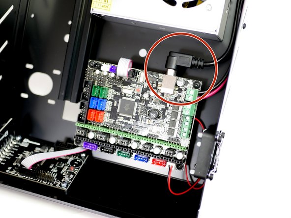
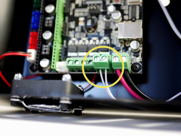
Fix the black and red power cables into the connector on the control board.
-
Orient the cables to the right as shown in the photo.
-
Connect Red to + and Black to - as marked on the board.
-
Make sure to insert the stripped section of the cable into the connector entirely and to fasten the set screw down TIGHTLY.
-
-
-
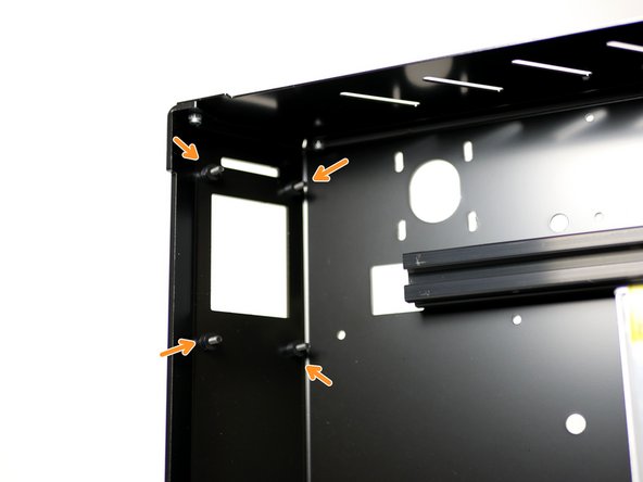
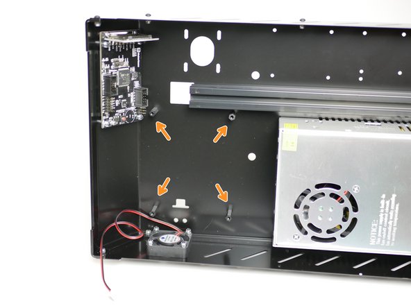
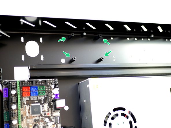
Fix four M3 standoffs onto the Base with four M3 x 6mm bolts.
-
M3 Standoff
-
M3 x 6mm bolt
-
-
-
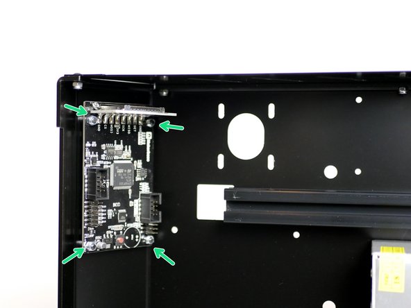
Fix the ribbon cable to the back of the touch screen display, route it under the control board and connect the other end to the board.
-
Secure the control board to the base with four M3 x 6mm bolts.
-
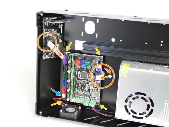
Plug the electronics fan cable into the white port on the control board next to the red connector.
-
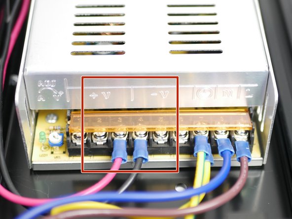
Securely attach the power cable connectors to the terminals on the power supply.
-
Red = +
-
Black = -
-
-
-
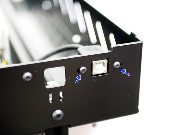
Fix the USB B cable to the back of the base with two M3 x 6mm bolts.
-
Route the cable along the side of the power supply.
-
Connect the other end of the cable to the control board.
-
-
-
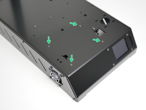
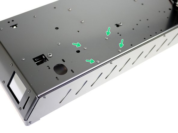
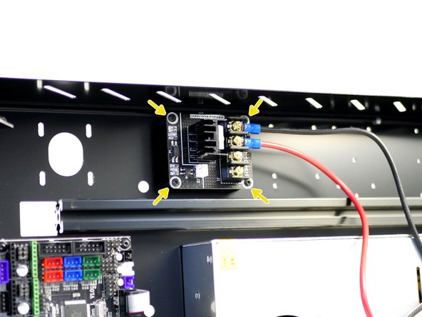
Fix four M3 x 15mm standoffs to the base with four M3 x 6mm bolts.
-
-
-
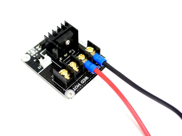
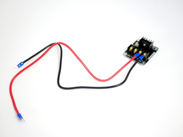
Fix the power cables to the MOSFET terminals.
-
Black = Negative (-)
-
Red = Positive (+)
-
Mount the MOSFET onto the base with four M3 x 6mm bolts.
-
Make sure the cables face towards the back of the base.
-
-
-
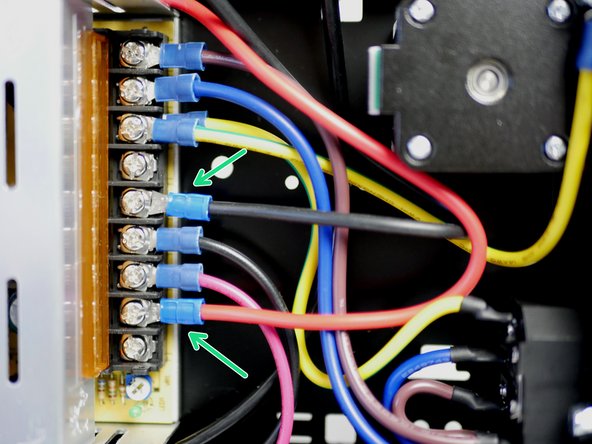
Connect the other ends of the power cables from the MOSFET to the power supply:
-
Black = Negative (-)
-
Red = Positive (+)
-
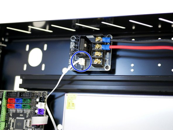
Connect the white cable (included in the MOSFET bag) to the MOSFET.
-
Connect the other end of the white cable to the control board as shown in the last image.
-
Which way round you plug the white cable in doesn't matter.
-
You may need to unscrew the control board from the base to get better access.
-


Cancel: I did not complete this guide.
31 other people completed this guide.
