
-
-
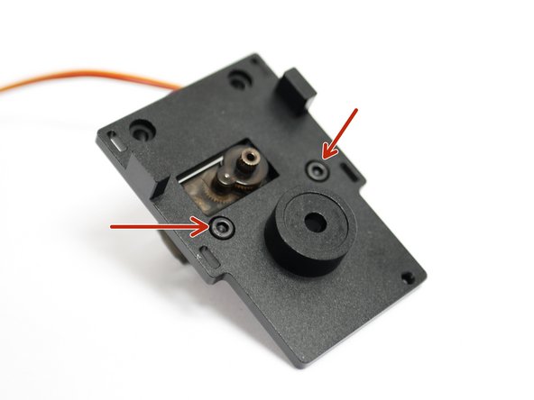
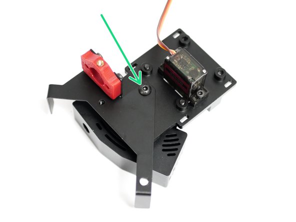
Use two M2.5 x 6mm bolts to fix the servo onto the backplate.
-
Make sure that the servo shaft is centrally aligned with the backplate.
-
-
-
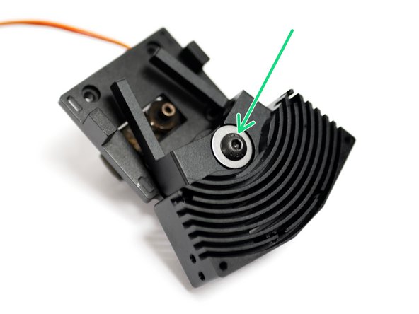
Insert an M5 x 20mm bolt with a needle bearing and shim.
-
M5 x 20mm Bolt
-
Thrust Bearing
-
Shim
-
On the other side of the heatsink slide on another thrust bearing.
-
-
-
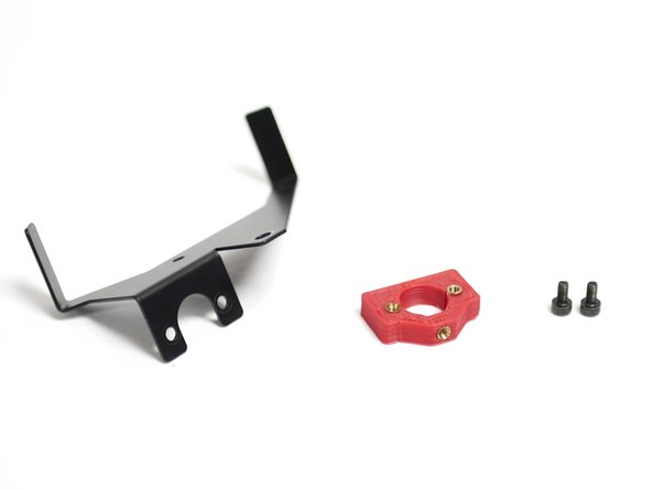
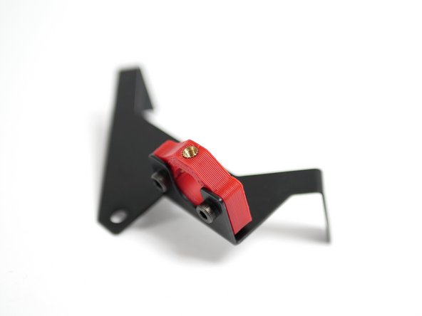
Begin by preparing the backplate with two M3 x 8mm bolts as shown.
-
Drop an M5 nut into the back of the Backplate.
-
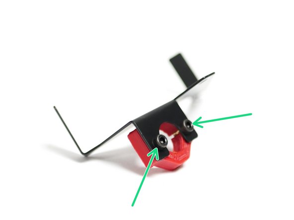
Fix the assembly together, making sure that there is no play in the switching motion.
-
The bolt should be tightened down enough to allow the heatsink to rock, but there shouldn't be any play along the axis of rotation or on the plane of contact.
-
-
-
When tightened firmly to hold the probe the threaded insert on the probe may pop out.
-
To prevent this from happening, use either a soldering iron or lighter to soften the plastic around the insert.
-
Then pinch the top and bottom of the mount to prevent the insert from popping out.
-
-
-
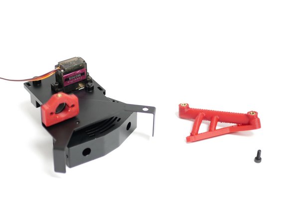
Fix the Probe mount onto the metal fan and probe mount as shown.
-
M3 x 8mm Cap
If you’ve not already done so please complete this form:
-
-
-
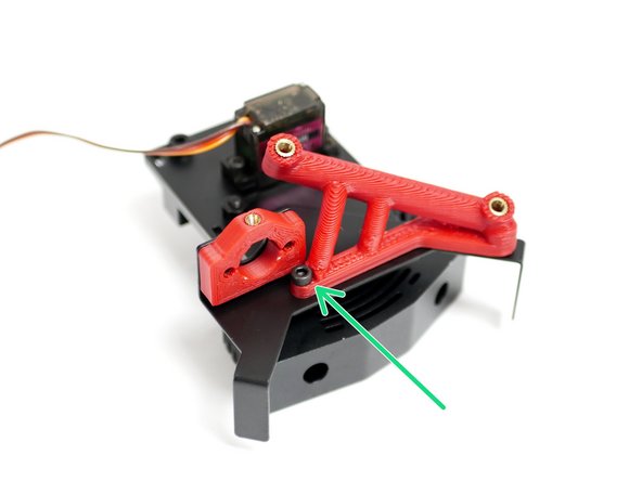
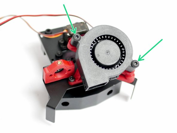
Fix the Probe and Fan Mount onto the backplate with just one M4 x 6mm bolt.
-
-
-
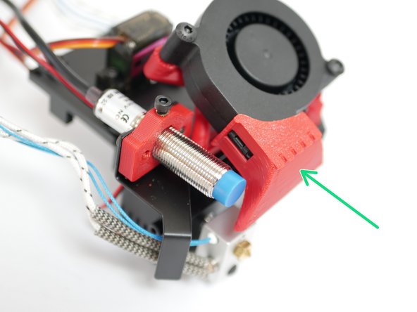
Fix the Angled Fan Mount to the Backplate with one M3 x 8mm bolt.
-
Remove the support material from under the angled fan mount before mounting.
-
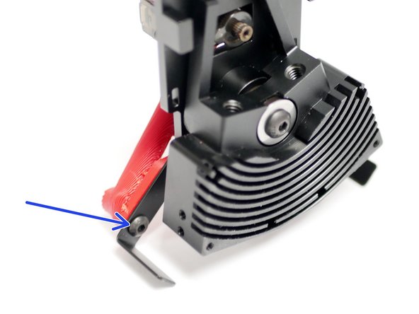
On the front of the assembly, use an M4 x 6mm bolt to secure the angled fan mount.
I ended up having to use an M4 6mm as the threaded insert thing on the printed part kept sliding out at the end.
I second the uploading of STL files; one part of my piece wasn’t flush where it is supposed to be bolted down, not sure if it impacts it at all.
My angled fan mount come with support material, I removed all support, I would recommend at later stage that u upload all Stl files for these 3 d printed parts
-
-
-
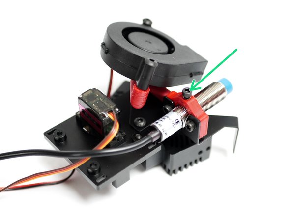
Insert the probe here and lightly secure it with an M3 x 8mm bolt.
-
We'll be adjusting the height of the probe later.
We’ve added this step here to prevent the insert from popping out.
My probe mount's thread insert was slided, and couldn't stable probe.
This parts should has been designed that insert was inside.
I designed new probe mount that use with Probe's original M12 Nut, then I printed with other 3D printer.
My designed parts is work correctly, and probe is stabled more strong.
I’d also like the .stl for this part. I need to redo the brass thread portion, but I might need to tighten up the hole a little to make sure it really bites.
We’ll have them uploaded soon!
Leveling prob come with 2 nuts and washers, do we need to dismantle them ( no usage)?
Yes, you can discard them.
-
-
-
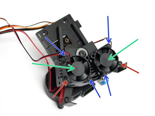
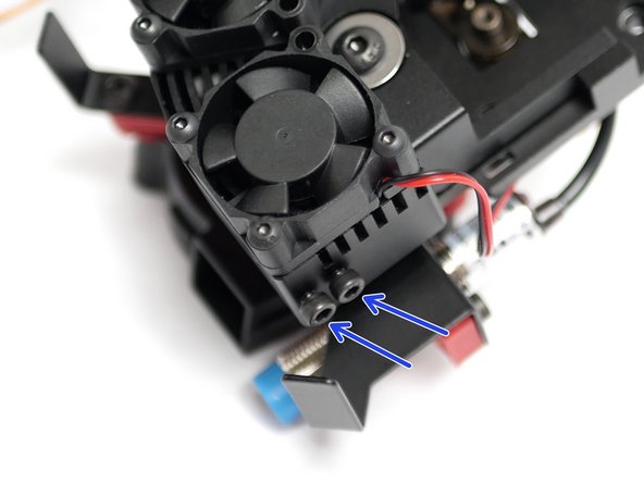
Fix the two 30mm fans to the heatsink:
-
M3 x 12mm bolt
-
M3 x 20mm bolt
Does it matter if it’s button head or cap head? I seem to only have cap head for these sizes.
Should not matter.
-
-
-
Take the two heater blocks and fix into them the two heater cartridges as shown.
-
Fix two thermistors to the blocks. We've shown two high temp. thermistors being installed here, but it is identical for the low temp thermistors too.
-
Make sure to match the orientation as shown in the photos. The two assemblies should mirror each other.
-
If you're installing a low temp thermistor, install it on the left hotend.
Got only one blue and other one is white !
Sorry, please use this form here, and we’ll have another sent out asap.
-
-
-
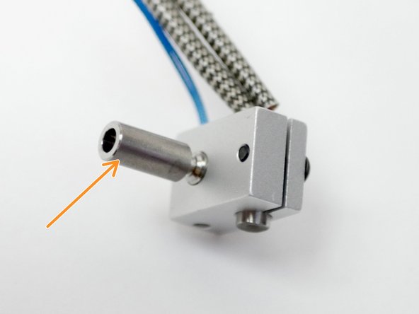
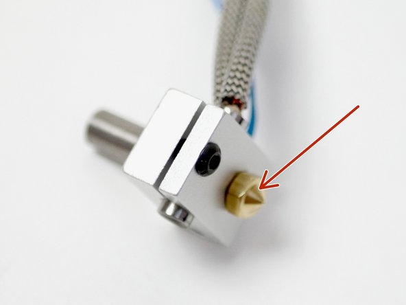
Fix onto both the heater blocks, the heatbreak.
-
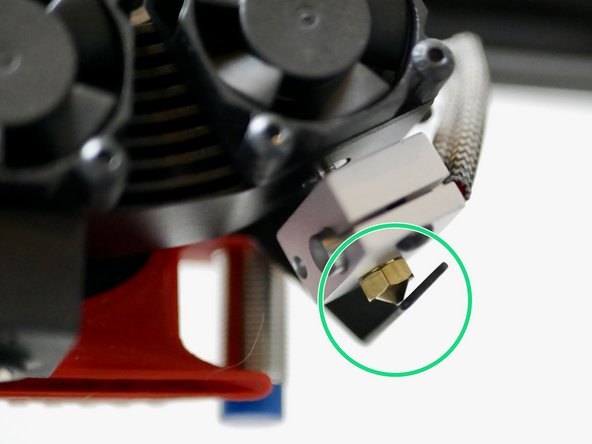
and the nozzle.
-
Make sure that the nozzle is tight against the heatbreak, but leave a slight gap between the nozzle and heater block when tightening. The nozzle will need to be tightened again when hot.
Actually got 4 , 2 with PTFE and 2 without . So which should I use?
Without the PTFE tubing is for the high temp setup, with the ptfe tubing it’s for use with the low temp setup.
Got 2+1 total 3, 2 of them does have PTFE tube inside .. shall I leave it inside or remove them?
-
-
-
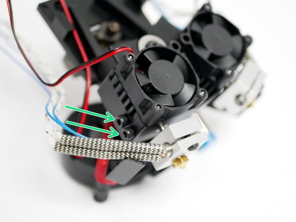
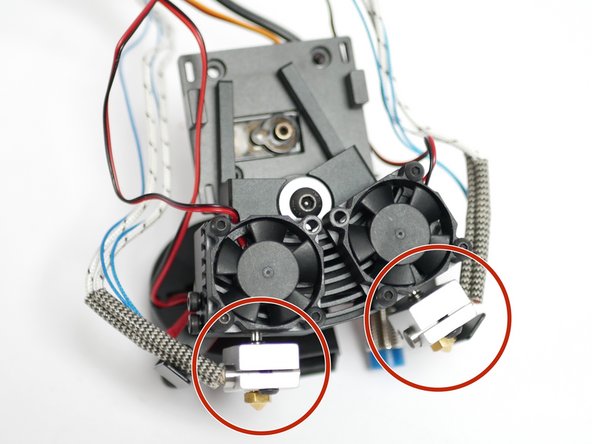
Prepare the heatsink by inserting two M3 x 12mm bolts onto each side.
-
Take the two heater block assemblies from the previous step and push them into the heatsink.
-
With the heater block assemblies pushed in all the way, tighten the bolts to secure them in place.
-
Note the orientation in the image. The heater side of the block should be facing forward.
No more M3 x 12mm ( extra 2 are needed) , why u did supply extra !
Apologies! Please use this form and we’ll have them sent out asap.
-
-
-
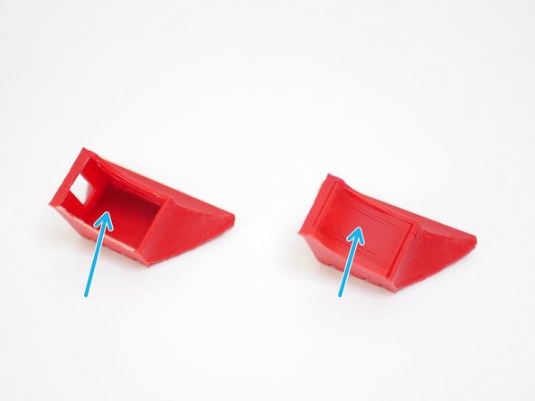
Break the support material away from the fan shroud.
-
Clip the fan shroud onto the blower fan as shown.
Got it cracked , please send me new good quality one , of course later I need the Stl file ( make sure it does fit the fan discharge)
Please use this form for replacement parts if you’ve not already.
-
-
-
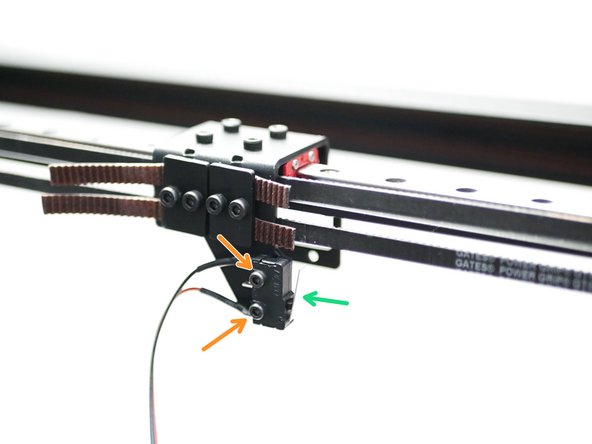
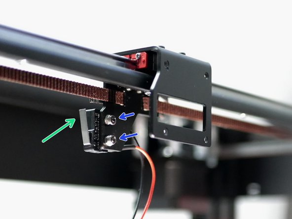
Install the X-Endstop as shown.
-
Note that the X-Endstop is the one with the longer 2M cable.
-
M2.5 x 12mm Bolt
-
M2.5 Nyloc Nut
-
-
-
Lay the DSH assembly onto the platform and arrange the cables as shown
-
Left Hotend and blower fan cables
-
Servo and Probe cables
-
Right Hotend cables
-
-
-
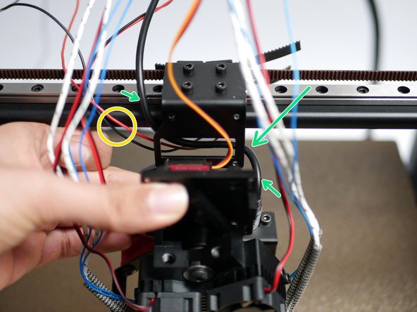
Bring the X-Endstop cable around to the front of the gantry.
-
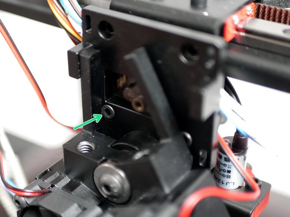
Route the probe cable behind the tool carriage.
-
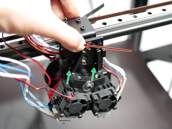
Push the servo into the hole in the tool carriage along with its cable.
-
Take the cables from the right hotend and place them over the servo.
-
-
-
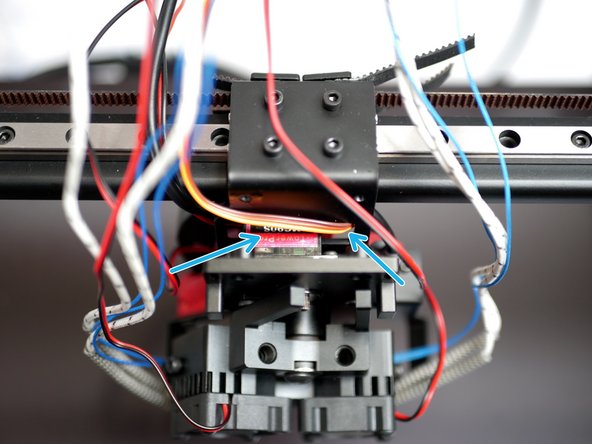
Press the DSH assembly onto the tool carriage, make sure that none of the cables are getting pinched.
-
Tighten the two M3 x 8mm bolts. Do this in alternation in order to allow the hotend to rotate out of the way.
-
Finally, use two M3 x 8mm bolts to completely secure the DSH to the carraige.
-
-
-
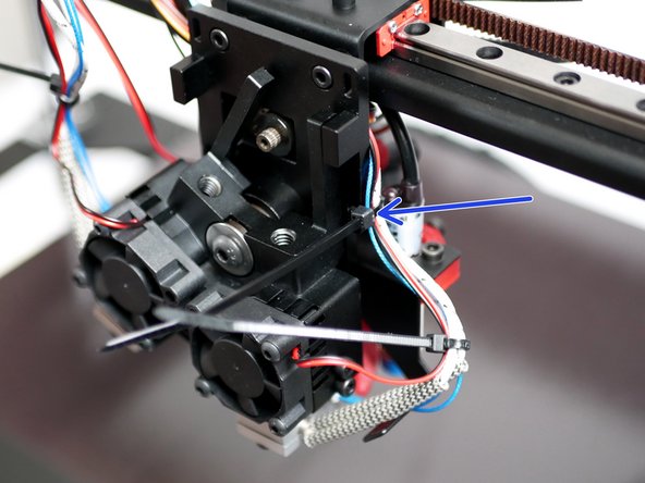
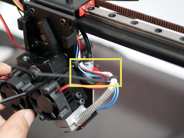
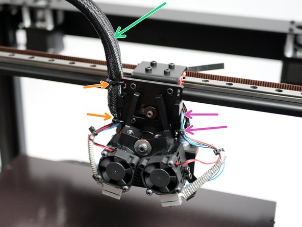
Cable tie together the heater, thermistor and 30mm fan cables from each hotend.
-
Cable tie the right hotends cables to the backplate also.
-
Ensure that when parked the highlighted part of the right hotends cables are horizontal.
-
-
-
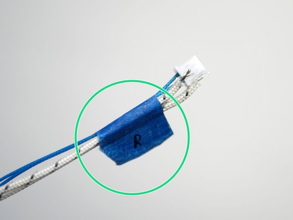
Use tape to mark, in this case, the right hotend heater cables and thermistor.
-
-
-
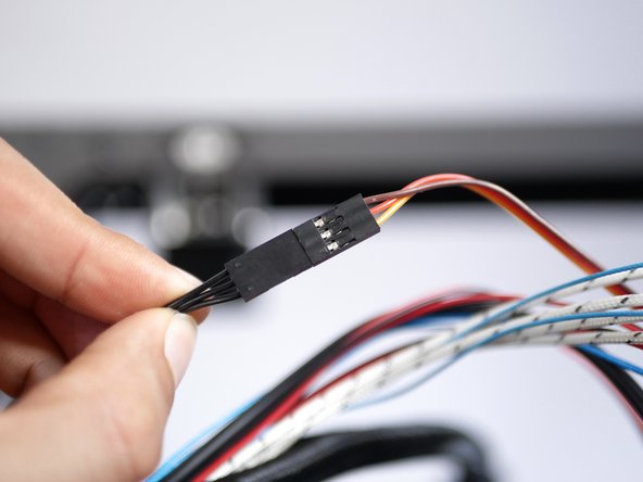
Take the hotend heatsink fan cables and use side cutters, scissors, or wire strippers to remove the connectors from their ends.
-
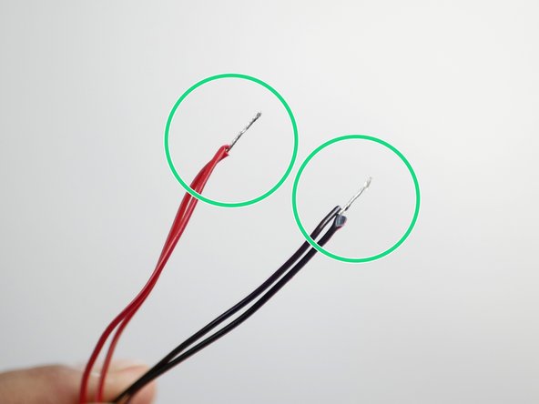
Strip away the outer sleeving to expose some of the wire.
-
Wrap the black and red wires together as shown.
Yes, that’s been made clearer now.
-
-
-
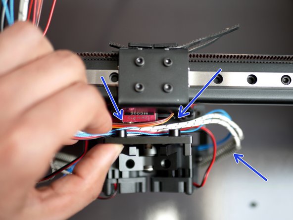
Wrap the cables with the braided cable sleeving.
-
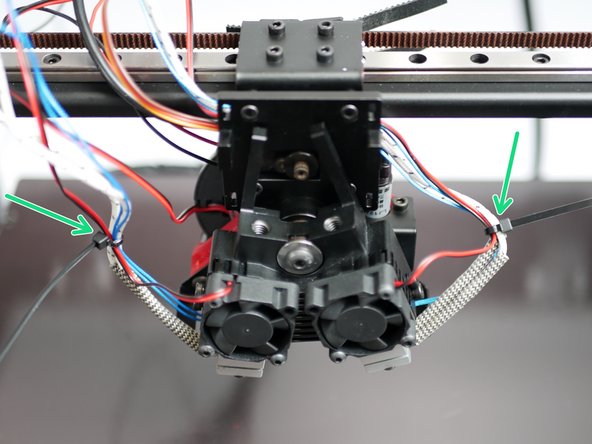
Cable tie the cables to the backplate as shown.
-
Cable tie the right side hotend cable to the backplate. Route these cables behind the backplate and into the sleeving.
What about the 2 wires coming from the other side, how they should goes? Could u hv a photo?
Updated with the pink arrows.
-
-
-
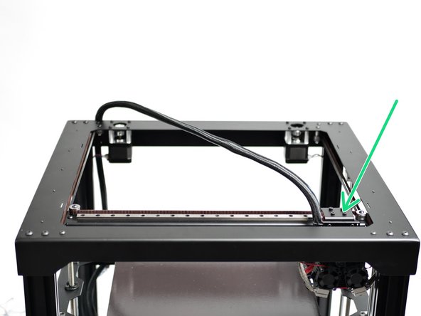
Push the tool carraige to the bottom left of the print area.
-
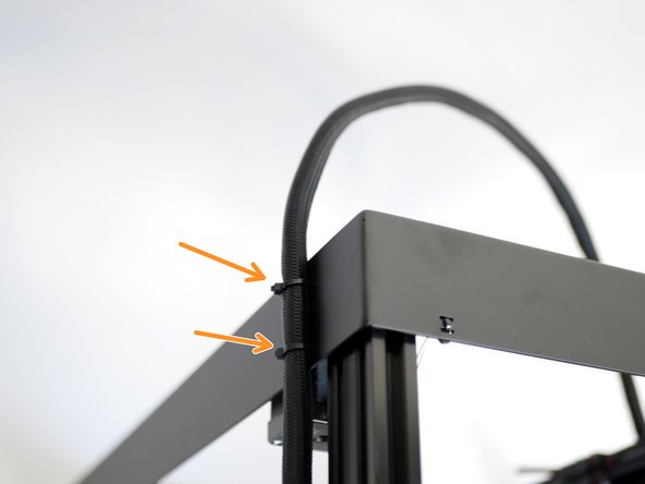
Use cable ties to secure the loom to the rear of the top panel.
-
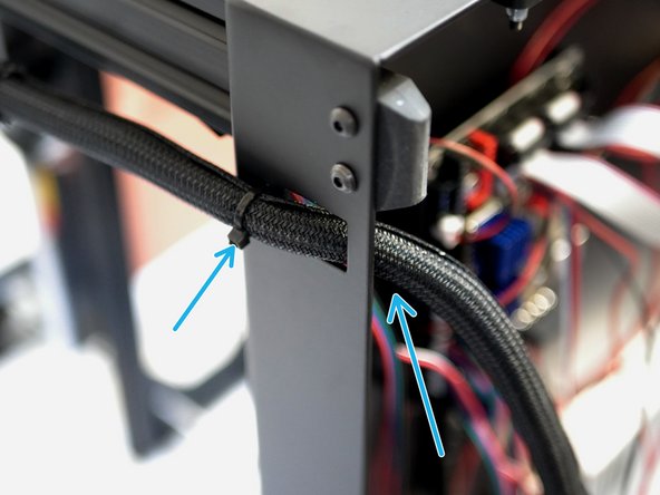
Feed the loom of cables into the base and secure with a cable tie.
-
-
-
Adjust the ooze shields by bending the metal sleds until they are able to make contact with the tips of both nozzles.
-
-
-
The Hotend covers simply slide in place over the heater blocks.
-


Cancel: I did not complete this guide.
4 other people completed this guide.

3 Comments
Did I miss a step somewhere on when and how you are supposed to attach the servo arm?!?!
It’s step 16 of stage 4.
That step is not in there. If you look at Step 14 of Stage 05 you can see a picture of it. You will use the printed brick red paddle, the M2.5 x 6mm cap bolt, and the M2.5 Locking Washer that is in the DSH - BAG A.
Jonathan -
My backplate wasn't drilled deep enough. I had to add 1mm washers between the bolt head and servo.
Peter - Reply
Where I can find this ? In which package or cartoon?
Wadi Ramahi - Reply