
-
-
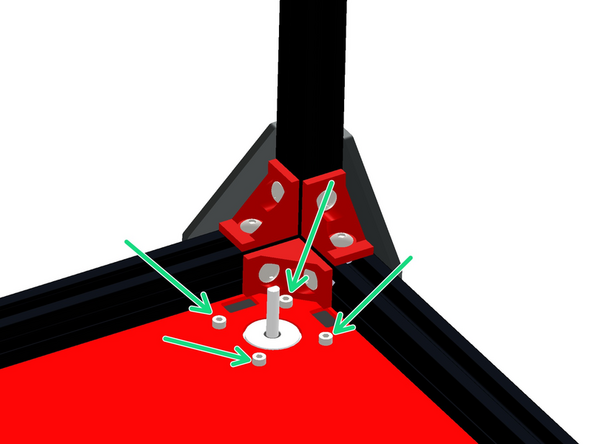
Prepare the base as shown:
-
M5 x 8mm Button
-
M5 T-nut
-
As before, do not tighten these nuts, they just need to be placed on by a few turns - they will be tightened down in the next step against the extrusions.
-
-
-
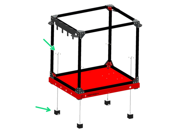
Secure the base to the bottom of the frame, orientating it as shown. Tighten the bolts from the previous step against the extrusions on the bottom of the frame.
-
Also add to each corner a rubber foot.
-
M6 x 75mm Bolt
-
Align the foot so that it slots in place into the cutouts on the base.
The easiest way to do step 2 is to place the frame upside down first. I don't understand the comments re. the bolts being too long – they screw into the extrusions, so could be crazy long and still work.
This step needs to happen before you tighten up the frame. Maybe a warning, early on, that the bottom bolts won't line up unless you loosen bolts on the frame. Also, I agree with Dave Bird. The M6x75s are too long. Now I have to either wait for Amazon or hope my local Home Depot has M6 x 25/35/40 bolts.
Start all four bolts in the rubber feet and only add a few turns to line them up. You need to have some space between the frame and the base. Otherwise, you will not have space to start the 4th and final bolt, as the hole in the base is less than a millimeter or so off. That is enough that you cannot run the bolt in if the base is pressed to the frame.
There are no M6x75 bolts that I can find. Bolts have hex heads. These are all button heads.
I agree... nothing listed as M6x75 bolts in any hardware bag. Just the button heads listed as M6x75. I used them and figured if I need more hardware to replace what I used I'll just purchase them.
Jeppy -
They are in the M5 bolt package
-
-
-
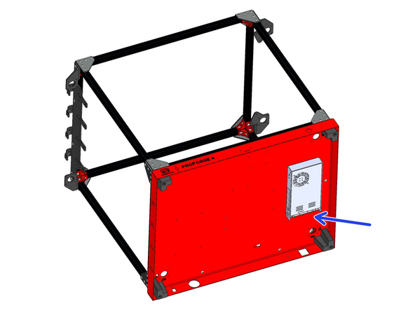
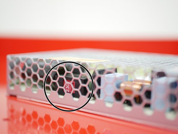
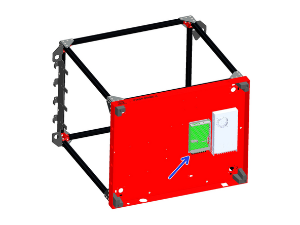
Before mounting the PSU, check that its voltage input is adjusted correctly. The switch on the side of the unit should be set to your mains voltage. For example, in Europe this would be 230v, and in North America it would be 110v.
-
-
-
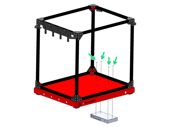
Mount the 24V PSU to the base.
-
M4 x 6mm Button Head Bolts
-
Ensure it's mounted with the terminals pointing to the rear of the machine.
-
-
-
Before mounting the PSU, check that its voltage input is adjusted correctly. The switch on the side of the unit should be set to your mains voltage. For example, in Europe this would likely be 230v, and in North America it would be 110v.
-
-
-
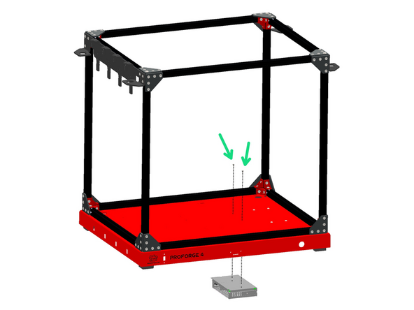
Mount the 48V PSU to the base.
-
M3 x6mm Cap Head Bolt
-
Again - ensure it's mounted with the terminals pointing to the rear of the machine.
-
-
-
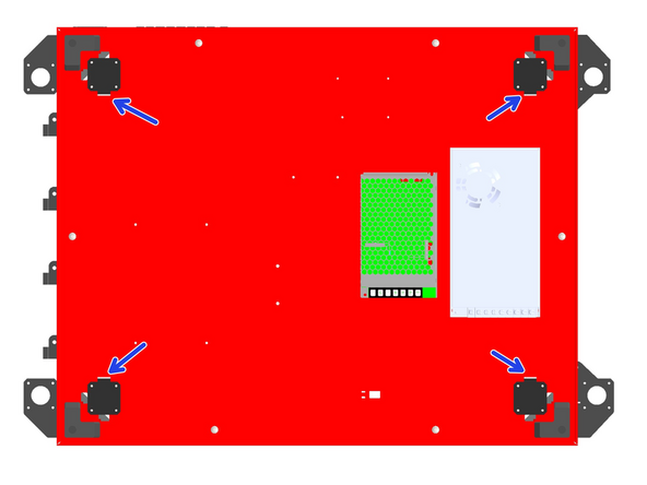
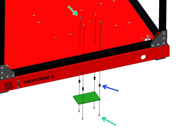
Mount the four NEMA-17 Motors to the base with M3 x 6mm cap head bolts.
-
These are the smaller BQ motors.
-
Ensure that the cable connectors on the motors are all facing inwards under the base as shown.
A double reinforcement. Make sure you use the smaller BIQU motors.
-
-
-
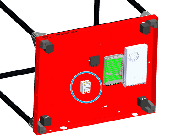
Mount the SSR Relay to the base.
-
M4 x 12mm Button
-
M4 Nyloc
-
Mount the SSR with the load side terminals facing the rear of the base.
-
Bolt orientation is purely aesthetic, feel free to install the other way round (easier), with the nut on the top side of the base.
It appears we are being asked to run the button heads thru from the top. This will cause the nuts to be inside the recesses in the SSR. I do not see a sound way to hold those nylock nuts other than by jamming a screw driver between the nut and SSR housing. I'm going to install the screws up from below and place the nuts on the top side. Hopefully, this doesn't cause an issue later.
I ended up doing the same.
-
-
-
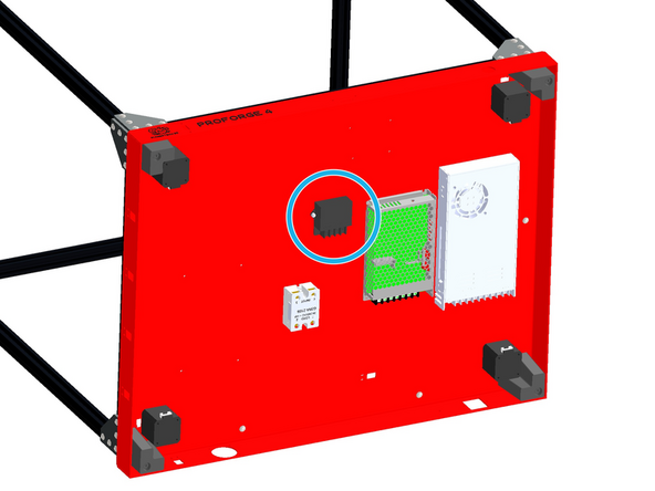
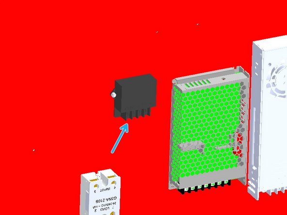
Mount the 5V Power Convertor to the base.
-
M3 x 8mm Bolt
-
M3 Nyloc Nut
-
Orientate the power convertor so that its terminals are facing the rear of the base as shown.
-
-
-
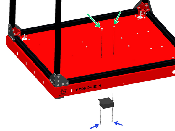
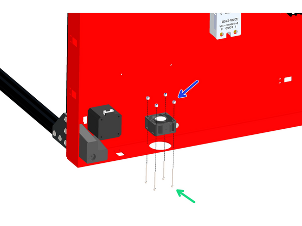
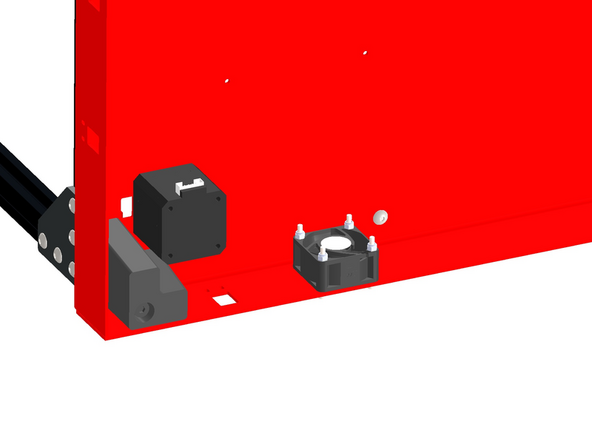
Mount the 40mm fan as shown - orientate the cable so it points to the top of the base.
-
Select the fan with the shorter (approx 20cm) cable.
-
Install the fan with the sticker side facing into the base.
-
M3 x 28mm Bolt
-
M3 Nyloc Nut
Something in the instructions saying which way the wire should go would be good.
Note that the wire faces down towards the ground / workbench the printer will eventually sit on. You can see the cutout for the wire in the diagram, but not the wire itself.
-
-
-
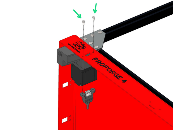
Mount the USB port to the front of the base as shown.
-
M3 x 6mm Cap Head Bolt
-
-
-
Before unpacking the Pi control board make sure that you have grounded yourself. You can do this by touching a large metal object. This is to prevent any static from damaging the control board when handling it.
-
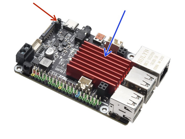
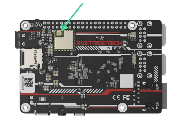
Stick the heatsink on to the Pi board.
-
Ensure that there is no jumper placed here - you may need to remove it.
-
Connect the WiFi antenna to the back of the board.
-
-
-
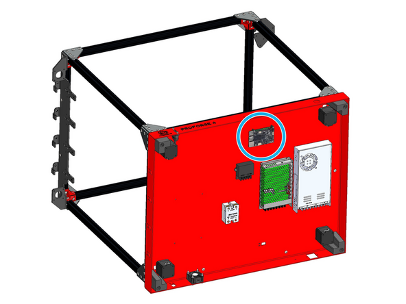
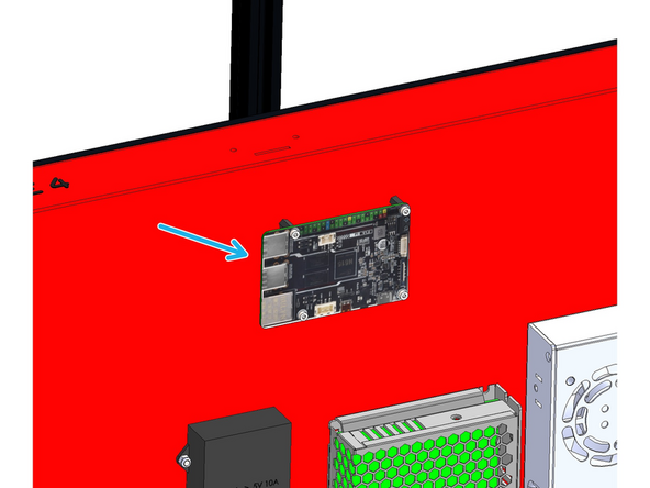
Mount the board to the base:
-
M2.5 x 6mm bolt
-
M2.5 x 10mm standoff
-
Mount the board with the USB ports pointing to the left as shown.
-
Do not stick the antenna to the base. We've been told by BTT that this can cause signal issues if it is stuck onto metal. Instead leave it hanging.
I recommend mounting the antennae away from the motors to limit interference
-
-
-
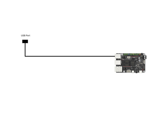
Connect the other end of the front USB port cable to a USB port on the Pi board.
-
-
-
Before unpacking the control board make sure that you have grounded yourself. You can do this by touching a large metal object. This is to prevent any static from damaging the control board when handling it.
-
After unpacking the control board you should find a bag of jumpers.
-
Use these jumpers to close connections between pins as shown on the diagram.
-
Set fan voltages to board voltage (24v)
-
Set thermistors to PT1000 (small jumpers)
-
Set gantry motors to 48V
-
Set all other motors to board voltage (24v) Installing these in the wrong position will cause damage to the drivers!
-
Make sure there is NO jumper placed on theUSB power pins.
The green jumpers (bottom left) are smaller than the rest (pins are closer together).
-
-
-
Before unpacking the stepper driver boards make sure that you have grounded yourself. You can do this by touching a large metal object. This is to prevent any static from damaging the drivers when handling them.
-
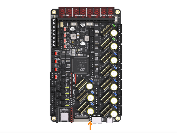
These drivers can only be plugged in one way. The fin side of the heatsink points towards the USB C port on the board.
-
With the board placed on a flat/hard surface, like a table, carefully push the motor drivers into their slots.
-
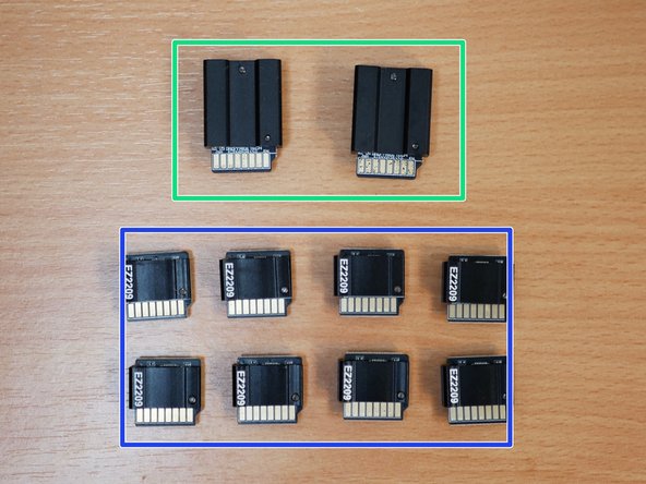
Plug the TMC5160 RGB EZ Drivers into the board as shown. They will drive the gantry motors.
-
Plug the TMC2209 EZ Drivers into the board as shown. They will drive the Z motors and extruders.
-
The extruder drivers are packed in with the print head bags.
-
You will have 4 for the z-motors by default and then one for each print head.
Thank you! I only lost 15min before checking comments.
the ez2209 are hidden: 4 in box a2, one each in every printing head bag. i searched 2 hours for the missing 4 ones...
-
-
-
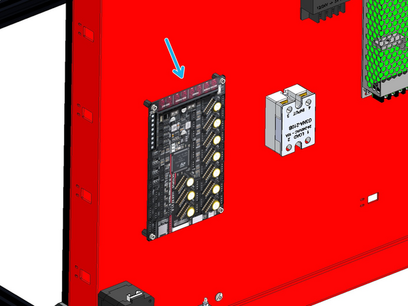
Mount the Octopus Control Board as shown:
-
M3 x 6mm Cap Bolt
-
M3 x 10mm Standoff
-
Orientate the board with the power terminals pointing to the front of the base.
-
-
-
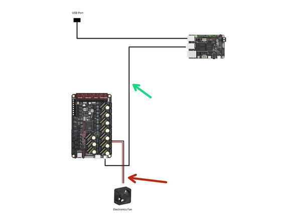
Connect the fan to the Octopus Max control board as shown.
-
Take the USB cable from the Octopus Max control boards box and connect one side to the USB C port on the control board and the other to a USB port on the BTT Pi.
-
-
-
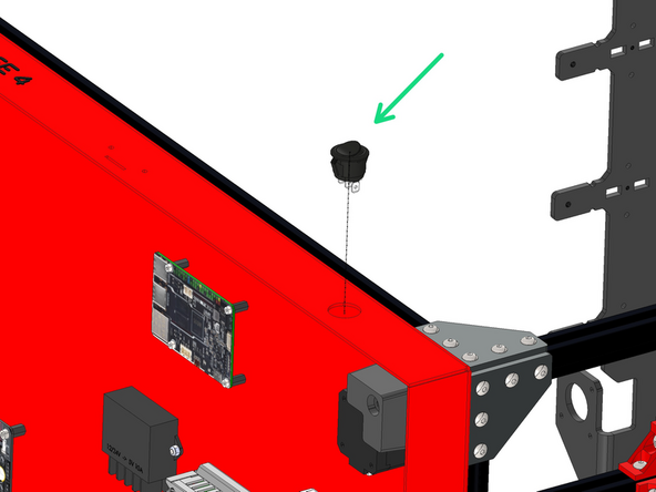
Disconnect the power switch from the mains power cable assembly. Push the power switch into the front of the base.
I just used a rotary tool with a straight carbide bit, kept vacuum close get filings, it took jut seconds.
I had no issues getting the power switch into the hole. No notch was needed. I will apply hot glue later if I find the power switch rotates with little effort to keep it in place. A notch would have been nice to have on the metal base to ensure no rotation of the power switch would happen.
it fits without notch by slighly pressure.
I used a metal file to make the missing notch.
There is an anti-rotation key on the switch but no corresponding notch in the hole.
-
-
-
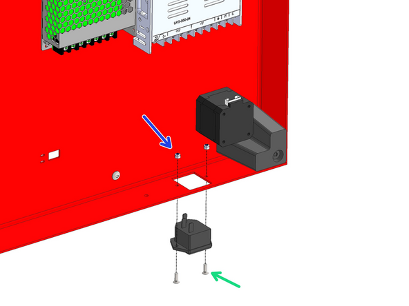
Fix the power port to the rear of the base.
-
M3 x 10mm Counter Sunk Bolt
-
M3 Nyloc Nut
-
Push all of the cables attached to the power port into the base.
-
-
-
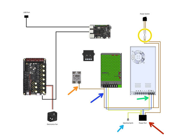
Connect the switch to the mains power port.
-
As shown in the diagram connect the cables from the mains power port to the:
-
24V Power Supply
-
48V Power Supply
-
SSR Relay
-
Fix the shortest earth cable to the base. Scuff the paint a little so that it is able to make contact with the metal.
-
M4 x 12mm button bolt and M4 Nyloc Nut
-
-
-
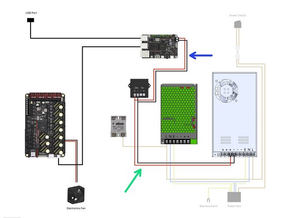
Wire the power converter and BTT Pi as shown.
-
Power Convertor cables - 50cm
-
Connect from 24V PSU to 24V terminals on converter.
-
Pi power cables - 30cm
-
Connect from 24v terminals on the convertor to the BTT Pi.
Twisting the power wires together about 1 twist per inch or so will add some rf frequency rejection and clean up the wiring. May not be needed but only takes a few seconds.
The 30cm PI Power wires actually don’t have terminals on the ends!!! Don’t clip off the terminals on one set of wires!!! Look for the red and black wires with one U-spade connector!!!
M4 x 12 Button
Wiring diagram is INCORRECT - the BTT Pi runs off 12V/24V DC input, unlike the Raspberry Pi which accepts 5v. The BTT Pi power cables should go to the 24V side of the power converter, not the 5V side.
For more info, refer to the BTT Pi user manual here: https://github.com/bigtreetech/BTT-Pi/bl...
You can use the 50cm/20in wire to connect directly to the 24v PSU
Thanks for pointing this out, the diagram has been corrected. The Pi should be powered with 24v from the 24v terminal on the convertor, not the 5v terminal.
Agree, I just realized the same thing. Saw an interview on youtube with Adeel (the founder of Makertech) Where he said just that. Some how didn't make it here.
-
-
-
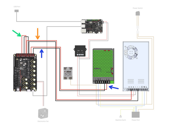
Fix the following power cables to the control board as shown.
-
24v Power Cables - 80cm
-
48v Power Cables - 70cm
-
Bed Power - 10cm
Now I'm gun-shy.
The blue and orange highlighted wires are confusing. In the diagram, the blue color highlighted wires actually coming out from 48V power supply but the description stated 24V power.
So, which one is correct?
Corrected - thanks for pointing out!
-


Cancel: I did not complete this guide.
17 other people completed this guide.

3 Comments
It might take only 45min-1hr for someone who is very familiar with this process. I'm guessing I spent 4 hours or so on this step. Of course, I read everything and double/triple checked everything.