
-
-
Prepare 24 of the Corner Brackets as shown.
-
M5 x 8mm Button
-
M5 T-Nut
-
Do not tighten these nuts, they just need to be placed on by a few turns - they will be tightened down later in the next step.
-
-
-
Assemble the corner of the frame as shown.
-
Take care in orientating the beams as shown.
-
600mm Extrusion
-
470mm Extrusion
-
Corner Bracket Assembly (x3)
-
Ensure the end of the 600mm Extrusion is flush against the sides of the other extrusions as shown.
-
Assemble a total of four of these.
I’m confused about which 600mm extrusion to flush. On the third picture, which extrusion do I see the bottom of?
Paul Platt - Resolved on Release Reply
It does pay to read the comments before starting. Thanks Brendan.
Brian Mettlen - Resolved on Release Reply
T-nuts should auto-rotate and "grip" the inside of the 2020 extrusion rails when you tighten them.
If they don't auto-rotate around it means you tightened the nuts too much before they were put into the rails. Try unscrewing them a bit and retightening them to grip the inside of the rails.
Brendan DeBeasi - Resolved on Release Reply
Don't spend too much time squaring the frame here. You're going to add brackets in the next step
Brendan DeBeasi - Resolved on Release Reply
-
-
-
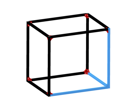
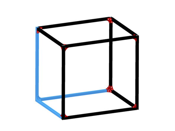
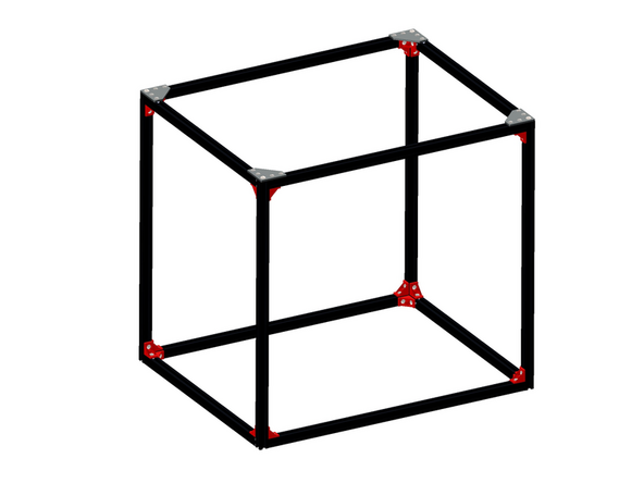
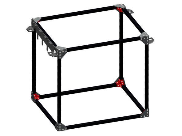
Assemble the four corner assemblies together to create the full frame.
-
The top portion of the frame where the gantry will run is the most critical when it comes to the frame being square. The rest of the frame is ok because the z-axis is designed to align itself with the top plane, irrespective of the frames squareness.
I used 90 degree right angle square rulers, Loctite thread locker and torque wrench
Dietmar Urban - Resolved on Release Reply
-
-
-
There are three types of L-brackets that look similar. We need to take the two types shown and described below. To these need to be added M5 x 8mm bolts and T-nuts.
-
M5 x 8mm Button
-
M5 T-nut
-
Do not tighten down yet, just fasten on the T-nuts by a few turns.
-
The first type has one 6mm hole in the corner as shown. (x4)
-
The other type only has 5mm holes around the edges. (x12)
-
The third - which is not used yet - has a threaded M4 hole on its diagonal edge. (x4)
-
-
-
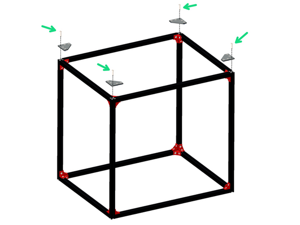
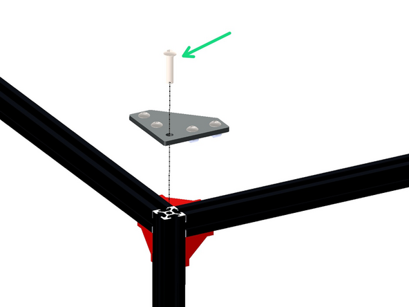
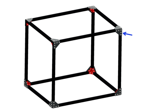
Fix the top brackets (these are the ones with 6mm holes in the corners) to the top side of the frame as shown.
-
M6 x 25mm Button
Don't bother fitting these is you have a v4.2 Proforge. This is becuase they will need removing to carry out step 18 of the 4.2 version of the gantry fitting steps.
Richard Thomas - Resolved on Release Reply
Might have to drill out the hole a bit for the M6x25mm to fit through the bracket.
I found it best to loosen the corner brackets from step two to get good alignment and then retighten the bolts on the corner brackets.
David Klingenberg - Resolved on Release Reply
-
-
-
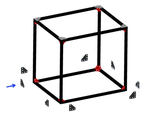
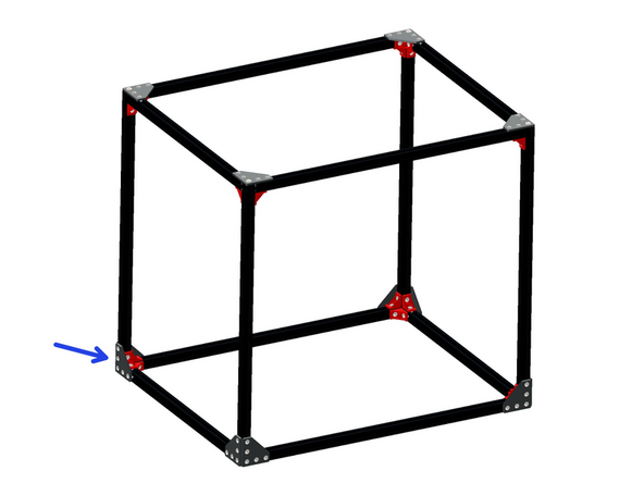
Next using the remaining bracket assemblies attach them around the base of the frame as shown.
I found it best to loosen the corner brackets from step two to get good alignment and then retighten the bolts on the corner brackets.
David Klingenberg - Resolved on Release Reply
-
-
-
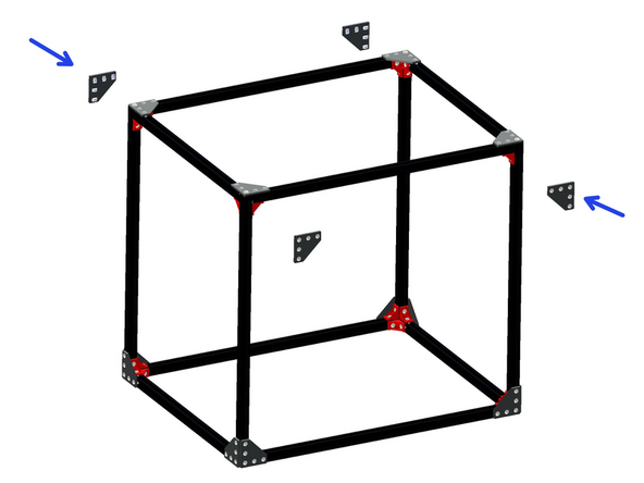
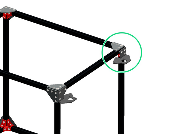
Fix the remaining four bracket assemblies to the top front and rear sides of the frame as shown.
-
These brackets go on the long edge.
I found it best to loosen the corner brackets from step two to get good alignment and then retighten the bolts on the corner brackets.
David Klingenberg - Resolved on Release Reply
-
-
-
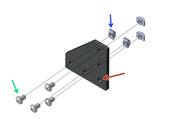
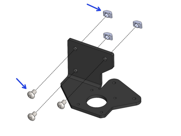
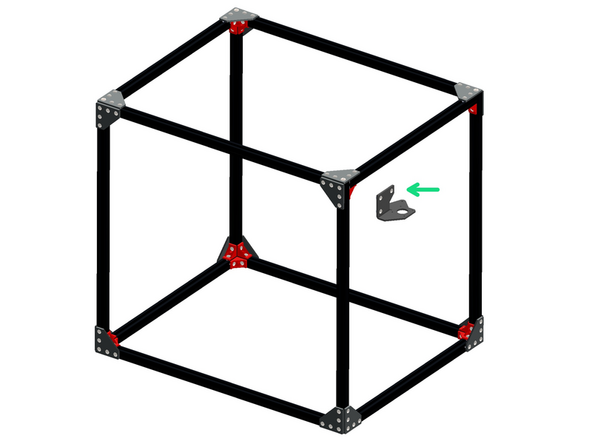
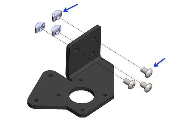
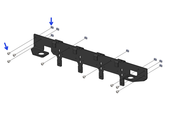
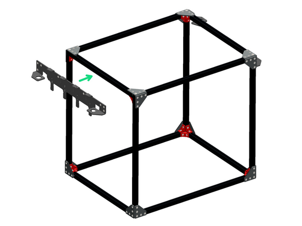
Prepare the Front Motor Bracket with M5x8mm Button bolts and T-nuts
-
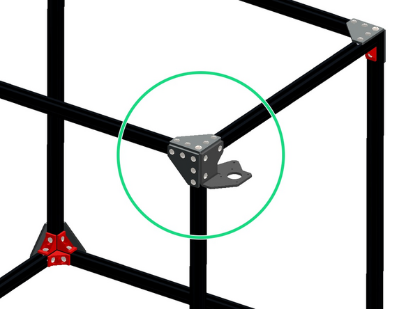
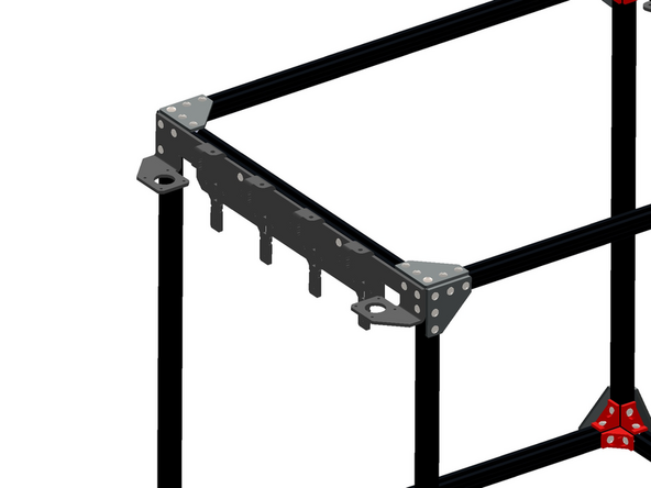
Fix the bracket onto the front right side of the frame as shown.
This is a good time to install the idlers do you don't have to remove and re-mount it again later in Stage 4. simply assemble the idler before you mount it first.
-
-
-
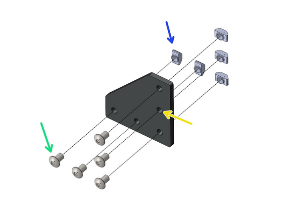
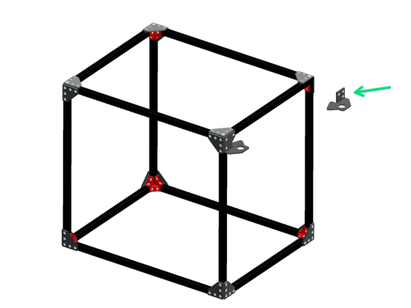
Prepare the Rear Motor Bracket with M5x8mm Button bolts and T-nuts
-
Fix the bracket onto the rear right side of the frame as shown.
-
-
-
Prepare the Tool Dock with M5 x 8mm bolts and T-Nuts as shown.
-
Fix the Tool Dock onto the Left side of the frame as shown.
-
-
-
Congratulations, you have completed the first stage of the build!
-


Cancel: I did not complete this guide.
20 other people completed this guide.

5 Comments
New record, done in 1 hrs 20 mins, 2 operators. thanks for the tips
Robert Dick - Resolved on Release Reply
I found it easier to loosen the three brackets slightly on each corner as I attached the corner plates. That allows the extruded bars to better align as you square the frame with the flat corner plates. Just don’t forget to tighten everything up after the corner plates are installed.
Dale Larsen - Resolved on Release Reply
The "00:30:00 - 01:00:00" time estimate is WAY too short, I spent 4-5h on this section alone, thanks to how much alignment/nut and bolt prep is required.
Same! I'd recommend getting everything mostly tightened until you have all the triangle brackets on, then tightend the red brackets.