
Introduction
Check the trouble shooting FAQ page here if you having any issues, you may be able to find a solution.
-
-
The Proforge 4 is powered by Klipper firmware which is an open source 3D printer firmware developed by the very talented Kevin O'Connor.
-
BTT/Raspberry Pi
-
The Pi board is an SoC (System On a Chip) board - essentially a mini-computer. It is what runs Klipper firmware and can be considered the "brain" of the 3D printer.
-
BTT Octopus MAX EZ Control Board
-
The Octopus board is a controller board. It takes instruction from the Pi board and controls the various components on the printer. It can be considered as the "nervous system" of the printer.
-
Each board has its own firmware. In this stage we will set up these two firmware's - starting with the Pi board.
-
-
-
Download the Klipper firmware image here.
-
Extract the file after downloading.
-
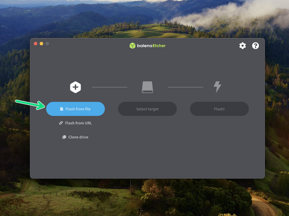
You will also need to download an image writing software. We recommend using Balena Etcher.
-
You will also need a text editor:
-
Windows: Notepad++
-
Mac: Sublime Text
-
-
-
Take the included 32GB SanDisk SD card and flash onto it the Klipper firmware image that you downloaded in the previous step.
-
Use Balena Etcher to do this.
-
The process will take roughly 10min.
-
After flashing keep the SD card plugged in for the next step.
-
-
-
The Flashed SD card should now show up named BOOT, open it.
-
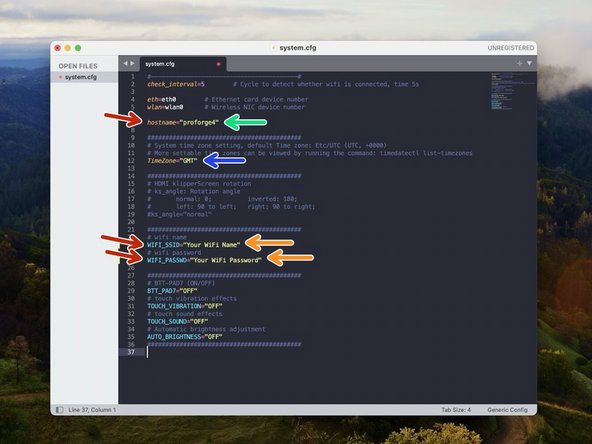
Go the system.cfg file.
-
Set the host name to proforge4
-
Set your timezone. Use the list here.
-
Input your WiFi networks name and password.
-
Make sure to remove the # at the front of the line to activate each section.
-
Save the file when done.
-
It is very important to safety eject the SD card when removing it. Not doing so could corrupt it.
-
-
-
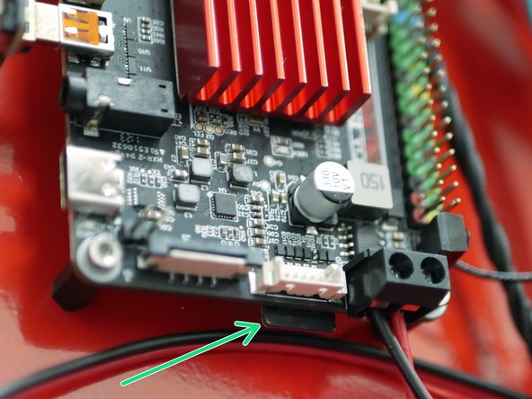
Insert the flashed SD card into the BTT Pi board as shown.
-
-
-
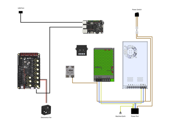
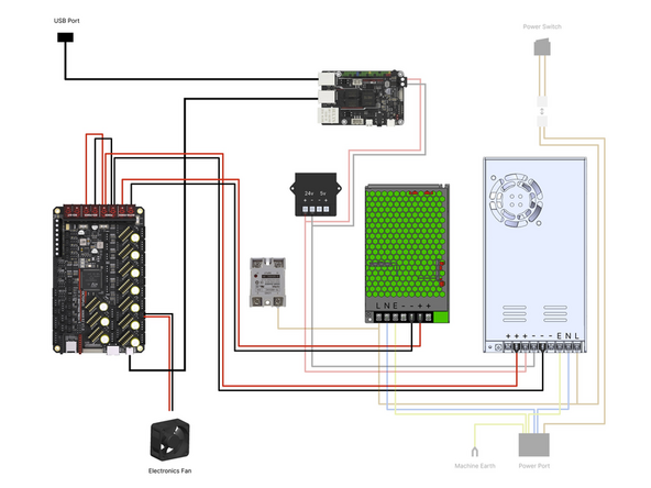
Check your wiring, in particular the mains wiring from the power port to the two power supplies and the wiring from the power supplies to the control boards.
-
Check that none of the cables are loose from their terminals.
-
Check the power supplies have their voltage input switches set to your mains voltage, 230V for Europe and 110V for North America.
-
When happy plug the cable into the back of the printer and flip the switch at the front to power up.
-
-
-
On first boot the printer may cycle through boot ups. If you have the touch screen installed, you will notice this on the screen.
-
When the printer has successfully connected to your network you will also be able to access it through a web browser that's on the same network.
-
You can do this by going to proforge4.local
-
It is normal to see an error here that the printer cannot connect, this is because we still need to upload our config files.
-
Also check that the electronics fan on the base and the print head fans are all spinning.
-
-
-
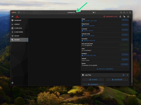
Before starting anything else we need to update the OS to the latest version.
-
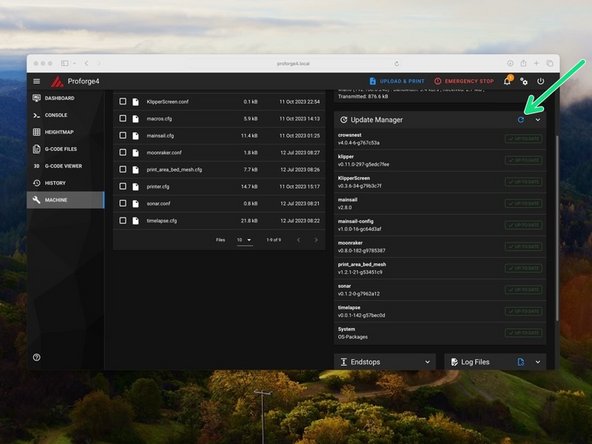
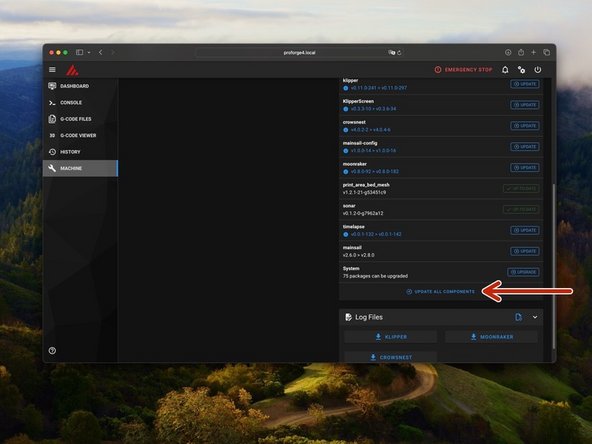
Do this by going to machine and then search for updates.
-
Then hit update - this can take few minutes and you may need to restart the process if there's an error which is normal, it will eventually complete.
-
-
-
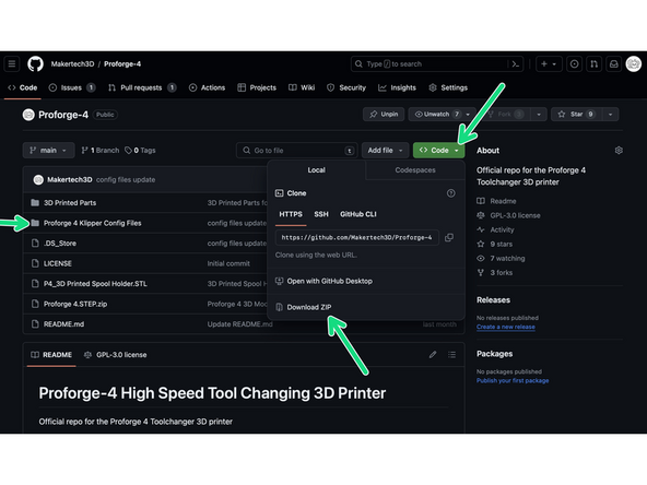
Download the config files from here.
-
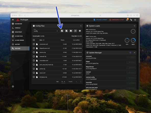
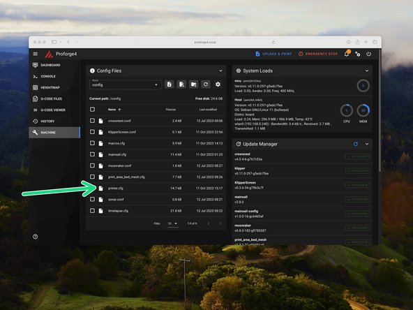
In the machine section click on the upload file button.
-
Upload the printer.cfg, macros.cfg, variables.cfg and S2DW.cfg files. Upload the Orbiter Filament Sensor config files also, if you have those sensors installed.
-
-
-
The firmware file for the Octopus board is something that needs to be created by Klipper on the Pi.
-
It's important that before starting this step you are running an up-to-date version of Klipper.
-
Major updates to future Klipper versions may require you to re-generate the Octopus boards firmware. Just follow these next few steps again in order to do this.
-
-
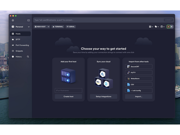
Termius is an incredibly useful SSH software that will allow us to access the Pi in order to generate the firmware for the Octopus board.
-
-
-
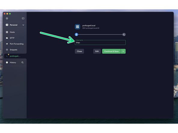
Install Termius and run through the set up wizard until you reach this dashboard.
-
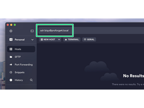
In the text bar at the top type in the following:
-
ssh biqu@proforge4.local
-
Make sure the printer is powered up and the Pi is connected to your network.
-
-
-
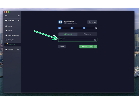
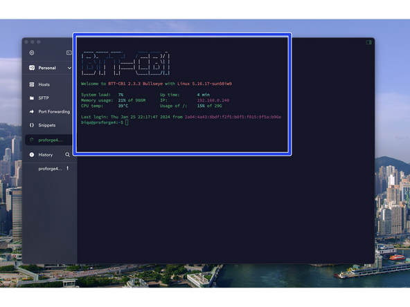
Enter biqu for both the username and password.
-
After successfully logging in you should see a screen like this.
-
-
-
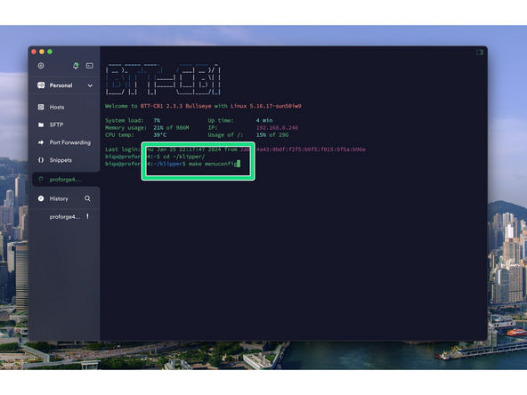
After logging in send the following commands to the terminal:
-
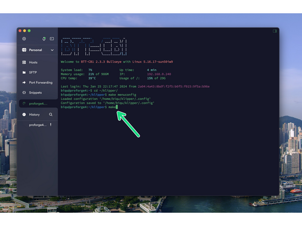
cd ~/klipper/
-
followed by:
-
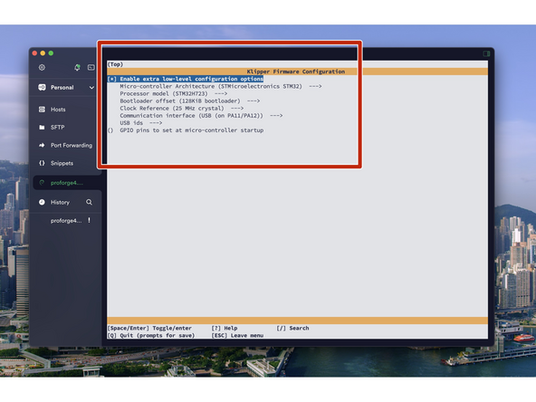
make menuconfig
-
You should now see a config menu, use the arrow keys on your keyboard to match the options selected in the image.
-
When done, press Q and then Y to save.
-
-
-
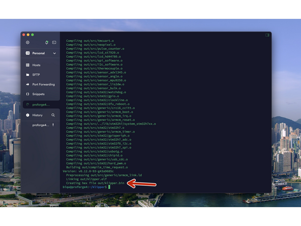
Send a make command to create the firmware file.
-
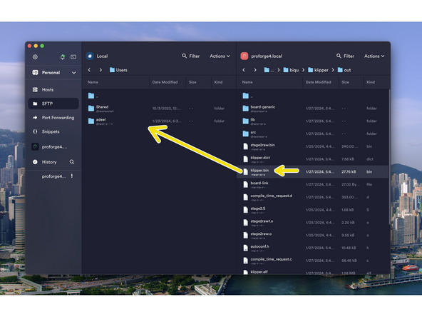
At the end of the process, you should have a klipper.bin file as shown.
-
-
-
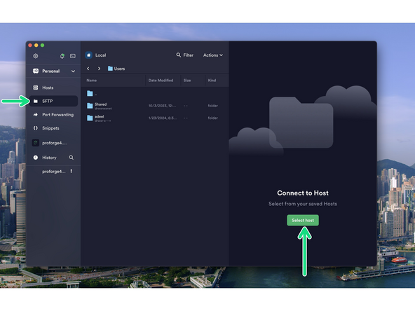
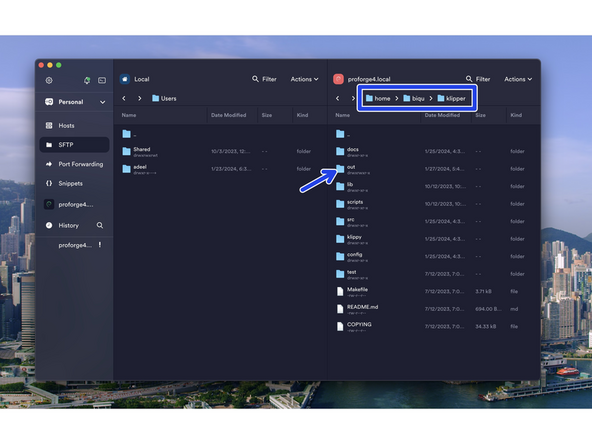
Go to the SFTP tab and press Select Host to open up the file browser for the Pi.
-
Navigate to the klipper.bin file by going to:
-
home -> biqu -> klipper -> out
-
Drag and drop the klipper.bin file to a folder on your computer.
-
-
-
Rename the klipper.bin file to firmware.bin
-
Take the micro SD card that came with the Octopus MAX control board and copy onto it the firmware.bin file.
-
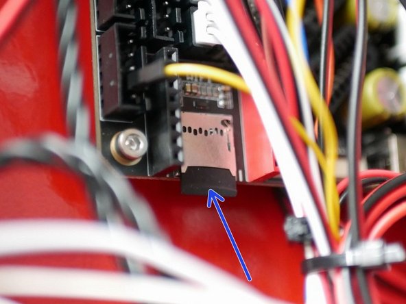
With the printer powered off:
-
Insert the SD card into the Octopus Max control board as shown.
-
Disconnect the USB cable that goes to the control board from the Pi.
-
Power on to flash the board
-
Wait a few minutes and then plug the USB cable back into the board.
-
-
-
Use Termius to SSH back into the printer in order to retrieve the boards serial id.
-
Ensure that the Octopus board is connected to the Pi via USB.
-
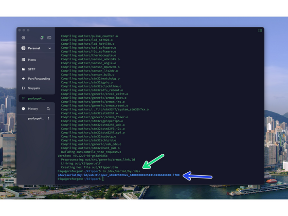
Find your unique id by sending:
-
ls /dev/serial/by-id/*
-
Copy the output to a notes or word file for now. We will need it later.
-
It should be written in the format shown. If you see the word MARLIN or FS_MODE in the id then the board has not flashed correctly - repeat the previous step. You can also plug the board directly into your pc to copy the firmware.bin file across, bypassing the SD card if it is causing issues.
-
-
-
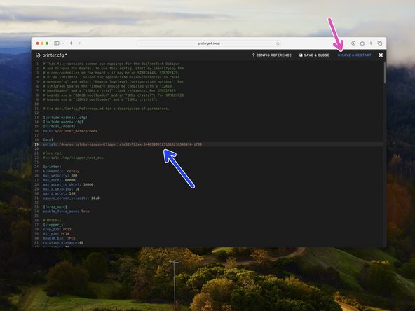
In mainsail open the printer.cfg file that you previously uploaded, by clicking on it.
-
Paste the line that you previously copied here, after serial:
-
Ensure to match the format as shown in the image.
-
Click Save & Restart when done.
-
-
-
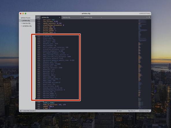
If you have less than all four of the print heads installed, you will need to comment out sections of the printer.cfg file as shown.
-
If you have just one print head, leave just the {extruder] section uncommented. Use a # infront of each line of the remaining [extruder1..2..3] sections that you don't have installed to de-activate them.
-
-
-
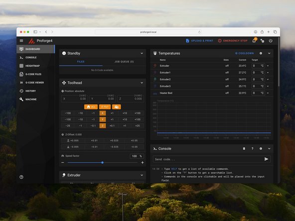
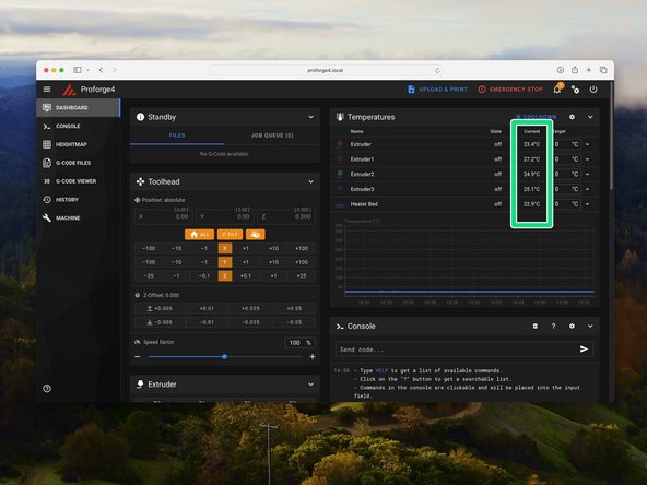
In the mainsail dashboard check that you are receiving the correct temperature readings for all installed print heads and heated bed - i.e. room temperature
-
-
-
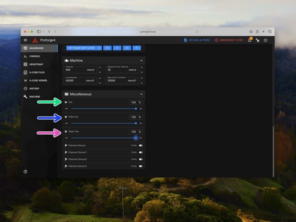
Set the part cooling fan to 100%
-
Set the static cooling fans to 100%
-
Set the filter fan (if installed) to 100%
-
Check that all of the fans are spinning.
-
-
-
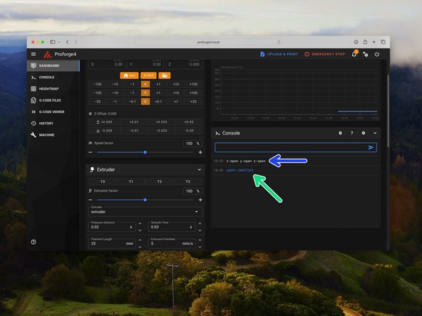
Make sure that none of the endstops on the printer are being mechanically triggered.
-
In the Mainsail console send the command QUERY_ENDSTOPS
-
The end stops should all return open.
-
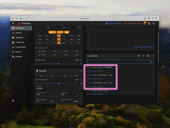
One by one, trigger the end stops and the probe (by placing a metal object under it) and resend the QUERY_ENDSTOPS command.
-
Verify that each endstop and the probe are functioning correctly.
-
-
-
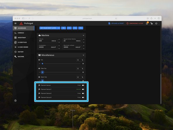
Scroll down the dashboard on Mainsail.
-
You should then see in the Miscellaneous box Filament Sensor readouts.
-
Load filament in to trigger the sensors and check that these are correctly updating.
-
Sensor 0 is the first extruder (nearest the front of the machine).
-
Sensor 1 is the second extruder.
-
Sensor 2 is the third extruder.
-
Sensor 3 is the fourth extruder.
-
-
-
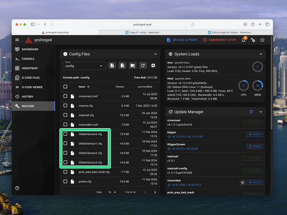
If you have the Orbiter Filament Sensors installed you will need to activate them in the firmware.
-
Check first that you have the OrbiterSensor.cfg files uploaded. They can be found here.
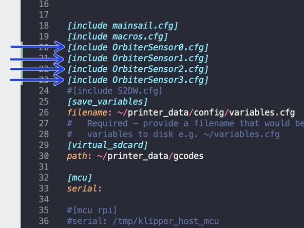
-
Go to the printer.cfg file and remove the # from the front of the sensors you have installed.
-
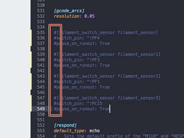
Scroll down and add a # to the sensors you have installed.
-
This will de-activate the externally mounted sensors.
-
Orbiter Sensors will auto-load filament and push button unload filament when the print head is selected.
-
-
-
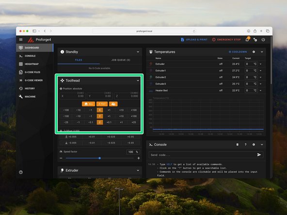
Manually move the tool head to roughly the centre of the print area. Also make sure that the platform is not set all the way to the top or bottom, but somewhere safe in the middle.
-
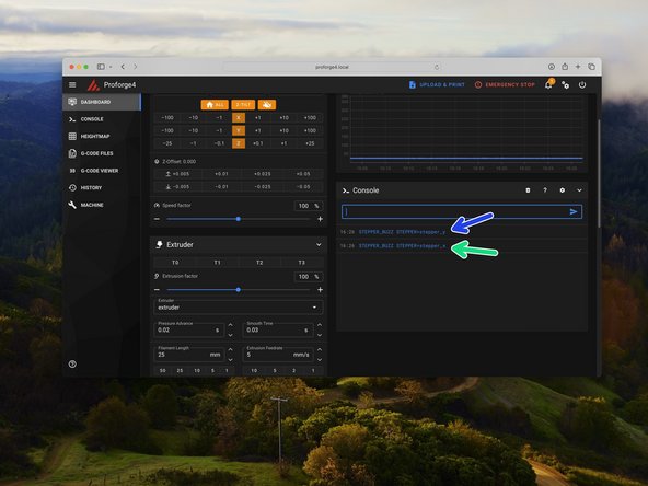
Send the command: STEPPER_BUZZ STEPPER=stepper_x
-
This will move the front left and rear right motors clockwise by a small amount and then return it to its original position. It will do this several times.
-
Send the command: STEPPER_BUZZ STEPPER=stepper_y
-
This will move the rear left and front right motors anti-clockwise by a small amount and then return it to its original position. It will do this several times.
-
If the above described movements do not occur, power down and double check you wiring.
-
-
-
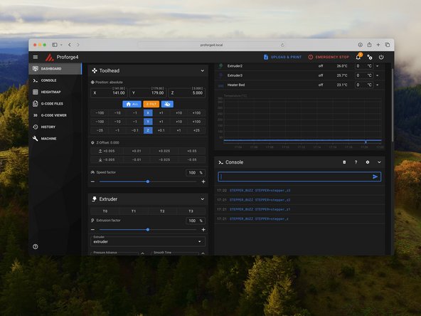
Send the command: STEPPER_BUZZ STEPPER=stepper_z
-
This will move the the z-motor in the front left corner anti-clockwise by a small amount and then return it to its original position. It will do this several times.
-
Send the command: STEPPER_BUZZ STEPPER=stepper_z1
-
This will move the the z-motor in the back left corner anti-clockwise by a small amount and then return it to its original position. It will do this several times.
-
Send the command: STEPPER_BUZZ STEPPER=stepper_z2
-
This will move the the z-motor in the back right corner anti-clockwise by a small amount and then return it to its original position. It will do this several times.
-
Send the command: STEPPER_BUZZ STEPPER=stepper_z3
-
This will move the the z-motor in the front right corner anti-clockwise by a small amount and then return it to its original position. It will do this several times. If the above described movements do not occur, power down and double check you wiring.
-
-
-
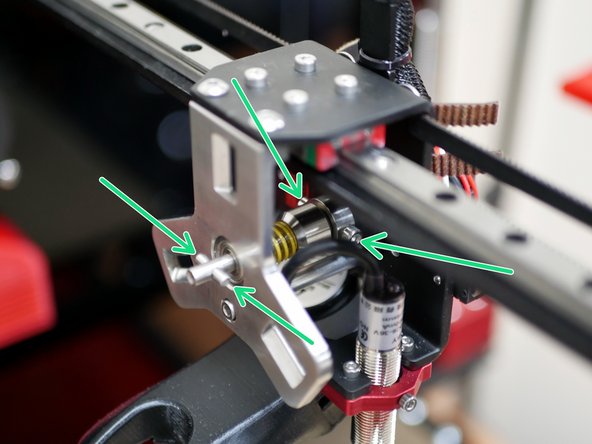
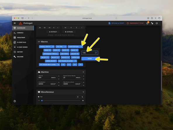
Before starting make sure that the bolts holding the drive shaft onto the servo are loose so that the servo shaft can move freely inside it.
-
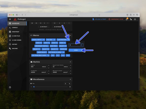
Go to the macros section in the control tab and set the servo angle (Cam Position) to 0 and hit enter.
-
You should hear the servo move.
-
Set the angle to 135 and then back again to 0.
-
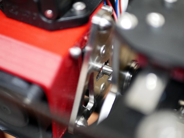
With the servo positioned at zero and the servo cam flat, tighten the bolts on the drive shaft down onto the servo gear.
-
-
-
Test the servo by sending a command to move it to 135 degrees.
-
The cam should rotate anti-clockwise.
-
Send another command to move it back to 0 degrees.
-
-
-
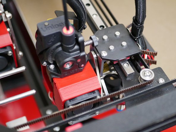
Manually move the tool carriage to a print head and slot the cam head into the tool plate.
-
Send a servo command to rotate the cam to 135 degrees.
-
The tool changer should pick up and hold the print head.
-
To release the print head, send a 0 command to the servo.
-
-
-
Before starting ensure the spring steel flexplate is placed onto the platform.
-
Attach to the carriage manually the first print head.
-
Move the print head over the print platform and manually raise the z-axis to meet it.
-
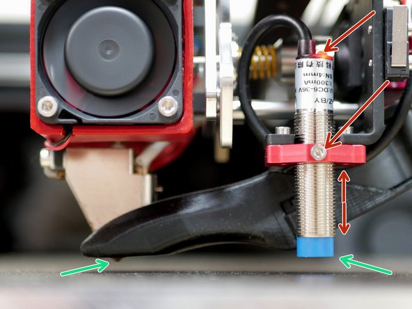
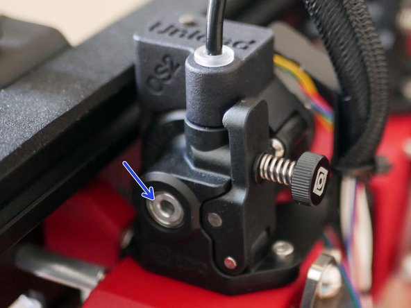
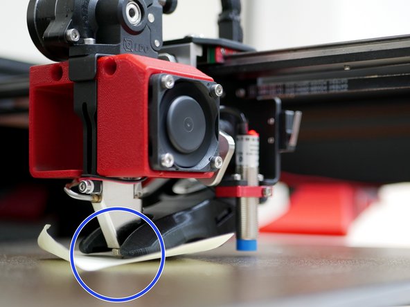
Adjust the probe height so that it triggers (red LED shines) before the tip of the nozzle touches the bed.
-
The bottom of the probe should be above the tip of the nozzle. But the probe should trigger before the nozzle touches the bed.
-
-
-
Check that all axes home correctly.
-
Home X, Y and finally Z.
-
Before attempting to home the Z axis, be sure the flexible steel build plate is installed. The inductive sensor will not pick up the bed correctly without it.
-
-
-
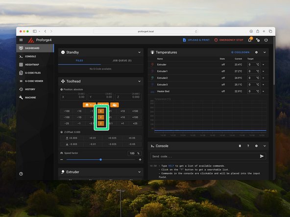
The pick up positions for each print head should be as follows:
-
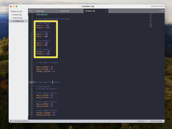
Print head 0 - X:-70 Y:14
-
Print head 1 - X:-70 Y:108
-
Print head 2 - X:-70 Y:201
-
Print head 3 - X:-70 Y:296
-
Use mainsail to check that these positions line up on your build and that the tool carriage is able to pick up all of the print heads and place them back.
-
Move the tool head incrementally as you get close to these positions, checking that the cam is safely slotting into each tool plate.
-
If you find that these positions need adjusting, they can be done so in the variables.cfg file.
-
-
-
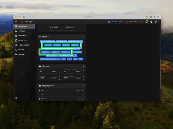
Use the macros to select and dock the print heads. Run through all of them making sure that the printer is able to safely select and dock each print head.
-
Note, take care when manually selecting and docking to avoid a crash. i.e. Do not select a print head whilst another is already selected!
-
-
-
At this point we can do some fine tuning of the printer by measuring input shaping values.
-
Follow the Input Shaping tuning guide here. Come back to this stage when done.
-
-
-
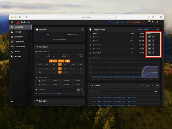
Heat up the print heads and heated bed as shown.
-
The thermistor values should increase as the hotends and bed heat up.
-
Keep an eye on your printer during this step.
-
The hotends and bed will be hot enough to cause burns, take care when operating.
-
-
-
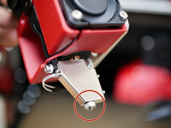
With the hotends hot, re-tighten the nozzles. This is called hot tightening and should be done when a new nozzle is installed to prevent leaks.
-
The hotend will be hot enough to cause burns, take care and never touch the hotend directly with your fingers!
-
-
-
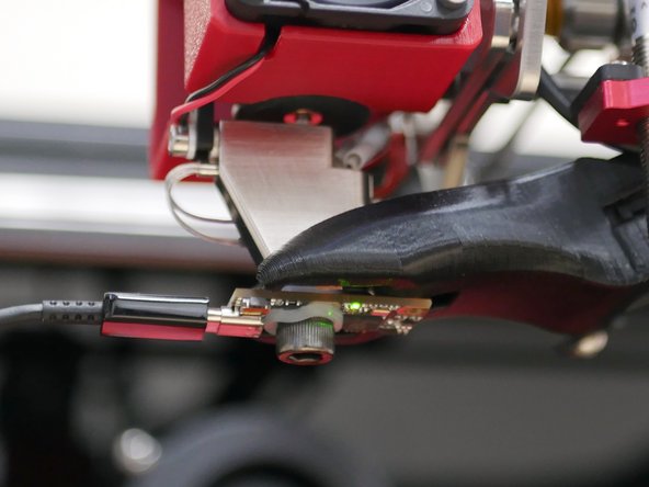
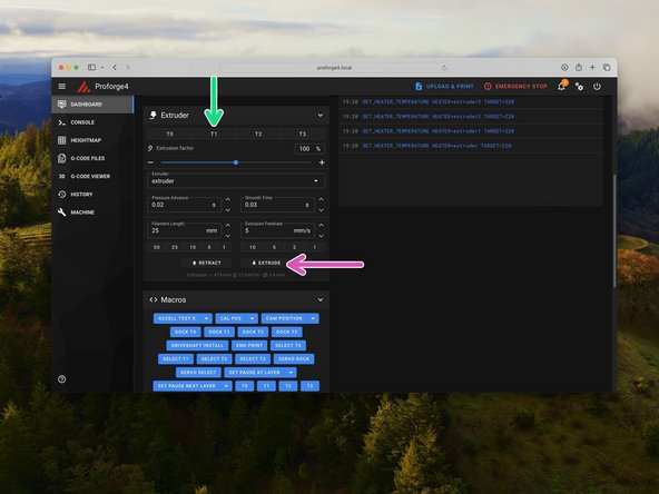
With the hotends hot, check that the extruders are all functioning.
-
Select and dock tool heads to cycle through the hotends.
-
Use the extrude button to turn the extruder.
-
After sending an extrude command the extruder should rotate clockwise.
-
Note, that the extruders will only turn when the hotends are hot (150C).
-
We recommend marking the front of the extruder here to be able to see clearly the direction the motor is turning.
-
-
-
Whilst the bed and first hotend are still hot we can set up the probe offset.
-
Home the printer and Select T0.
-
Move the print head to the centre of the bed.
-
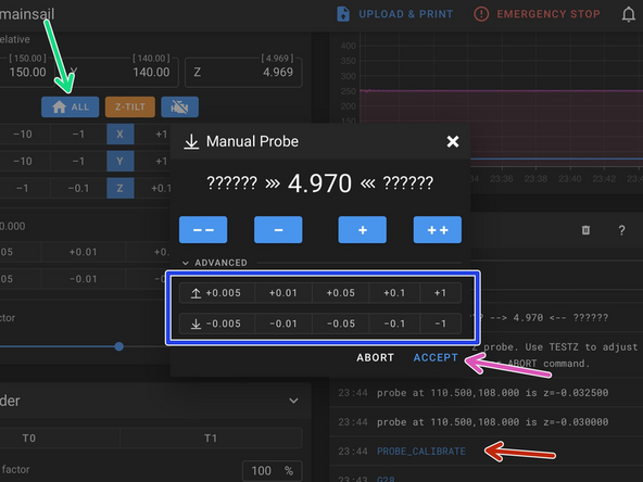
With the print head now in the centre of the print area and with the hotend and bed hot send the command PROBE_CALIBRATE
-
Place a piece of paper between the nozzle and the platform. Use the wizard to raise/lower the nozzle. Stop once it grips the paper.
-
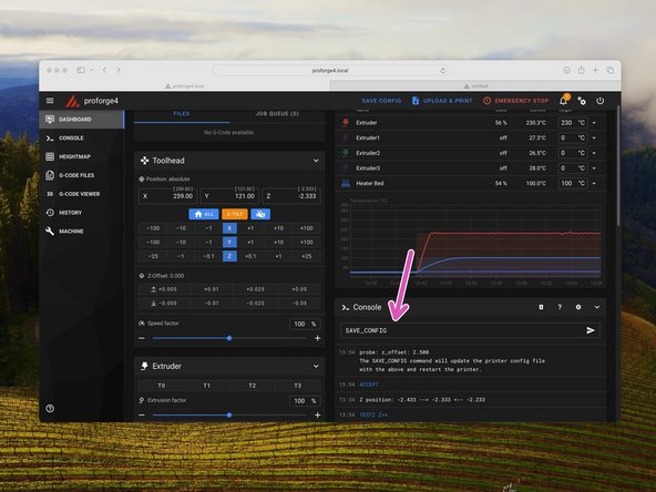
When happy hit accept. Send the SAVE_CONFIG command to save the offset.
-
-
-
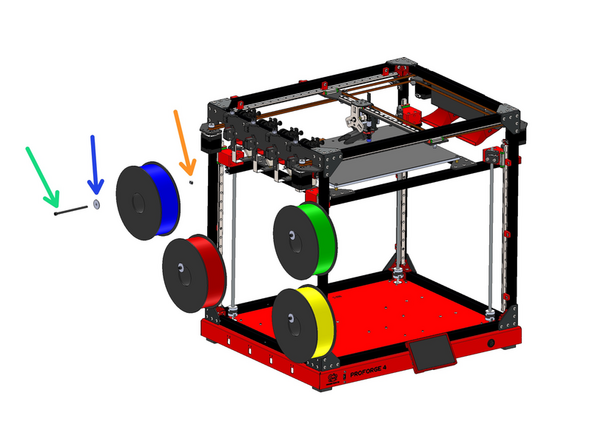
Attach the spool holders to the left side of the frame. The spool holders are made up of the following:
-
M5 x 100mm Bolt
-
M5 Penny Washer
-
M5 T-Nut
-
These bolts were missed out from the first batched have since been shipped to everyone that has a machine from the first batch. If you have not received a separate packet with these bolts please get in touch with us at info@makertech3d.com.
-


Cancel: I did not complete this guide.
11 other people completed this guide.
