-
-
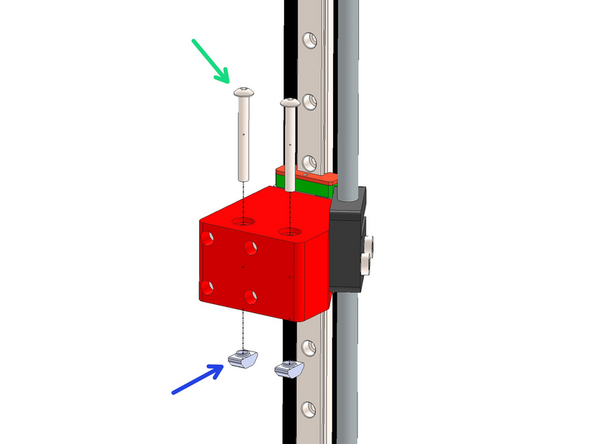
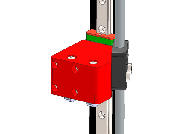
Prepare 12 rail mounts as shown by loosely fastening a T-nut onto the M5 bolt.
-
M5 x 8mm Button Head
-
M5 T-nut
-
-
-
Fix the mount assemblies from the previous steps onto the four 460mm long MGN12 rails.
-
Space them out as shown with two fixed one forth edge and the third in roughly the middle.
-
M3 x 6mm Cap Bolt
-
Use the orange stoppers to prevent the carriage from falling off the rail.
The red mounts should be placed one hole from the top, one hole from the bottom, and 10 holes from the top or bottom, which is the middle. Disregard the number of holes in the photo as it is inaccurate
Brendan DeBeasi - Resolved on Release Reply
-
-
-
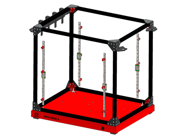
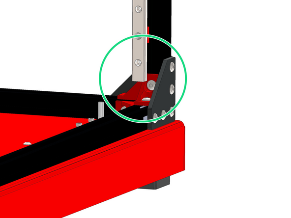
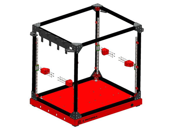
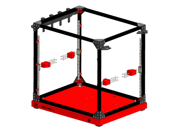
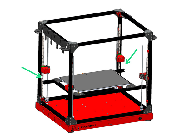
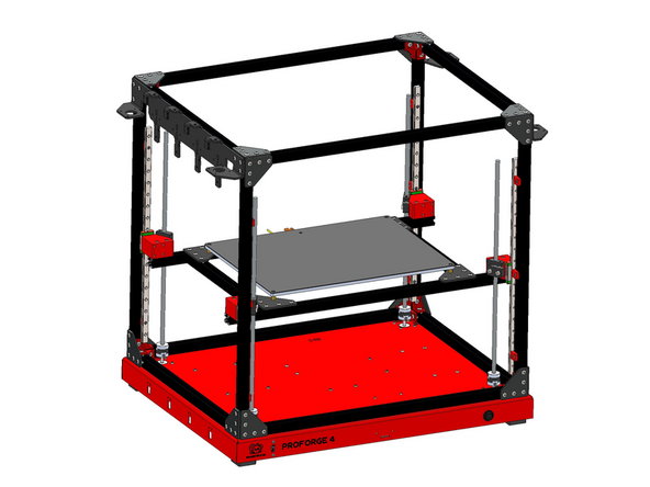
Mount the rail assemblies onto the inside of the frame as shown.
-
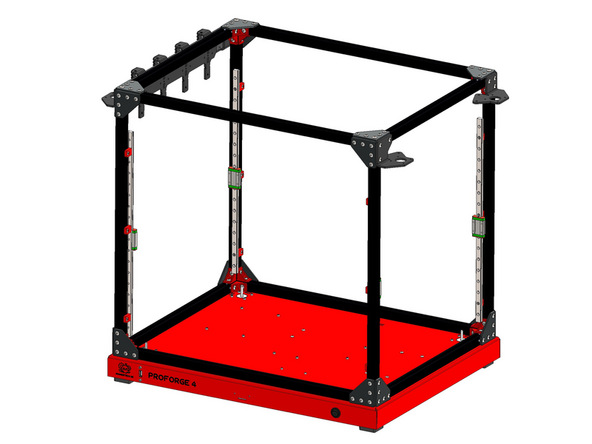
Mount the rail assemblies onto the inside of the frame as shown.
-
-
-
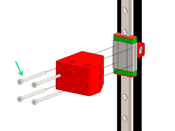
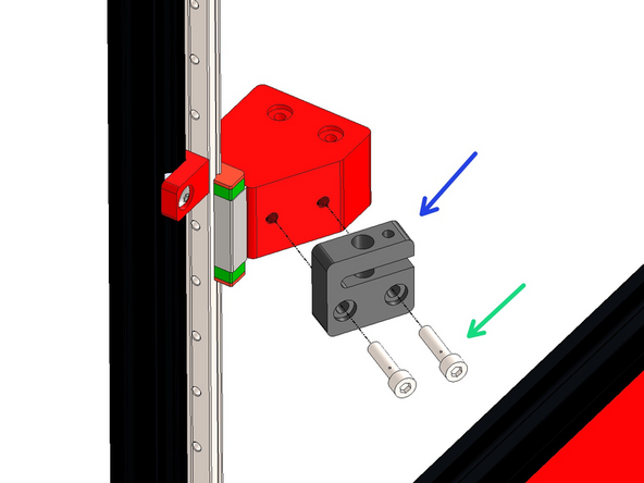
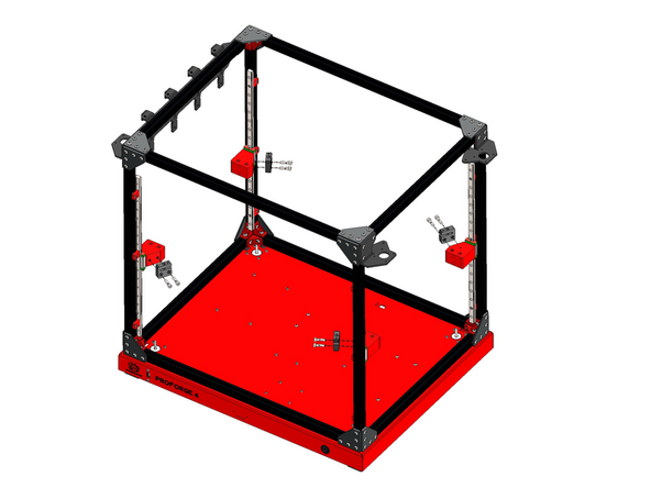
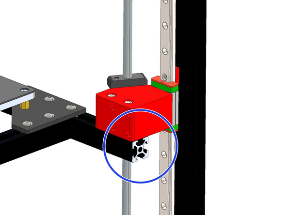
Mount Z-brackets onto the rail carriages with M3 x 45mm Cap Bolts.
-
Match the orientation of the brackets as shown in the images.
-
-
-
Fix the lead screw nut onto the bracket.
-
M5 x 20mm Bolt (Button head - image is incorrect)
-
Orientate the nut as shown.
If 20mm cap heads are too long then perhaps we're meant to use the button ones? I'm using them for now and I'll see what happens later in the build...
It would be good to hear what @makertech3d 's take on this? (There are no M5 20mm cap heads that I can find, only button-heads)
Mark Wheadon - Resolved on Release Reply
M5x20mm button heads are what are included in the kit, the cap heads in the image are incorrect - apologies for the confusion.
No description, depiction ,or explanation for the grub screw and single nut. Newbies may be seriously confused!
Dale Larsen - Resolved on Release Reply
I tried a 20mm Bolt head screws: Because the head could now enter the "sink" hole in the plastic part the thread of the 20mm bolt head screw is now too long. A 16mm bolt head screw will do the job.
Claus Ziegler - Resolved on Release Reply
In my kit there are no these type of M5 bolts but only the button ones. The problem is that the bolt head does not pass through the recess of the indicated plastic plug.
"En: In my kit there are no this type of M5 bolts but only button ones. The problem is that the bolt head does not fit into the recess of the indicated plastic plug."
I ended up using some M5 cap head I had
You could probably drill out the recess for the button head to fit, but the threads should reach most of the way
-
-
-
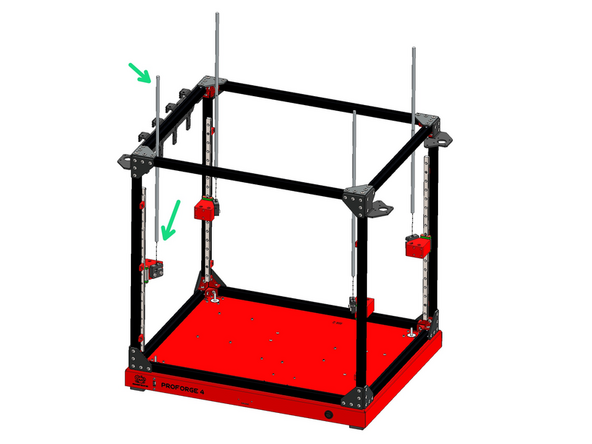
Feed the four lead screws into the nuts as shown.
-
-
-
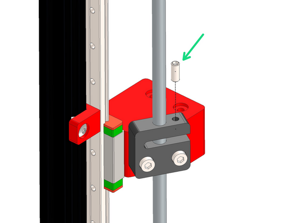
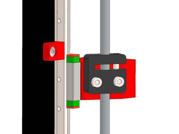
Add the M5 x 12mm Grub screw to the lead screw nut as shown.
-
Tighten until you feel some resistance, the purpose of this grub screw is to prevent backlash along the nut and lead screw.
-
Do not tighten to the point that the lead screw will no longer turn. You should still have smooth rotation of the lead screw through the nut.
-
-
-
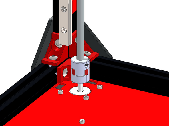
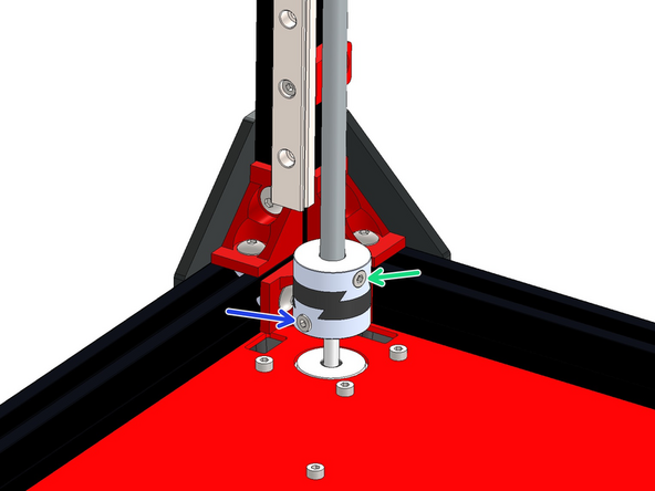
Fix the lead screws to the Z-motors with the plum couplings.
-
Tighten the bolts on the coupling to fix in place.
-
If you have the upgraded Oldham Couplings please see the next step.
-
-
-
Fix the lead screws to the Z-motors using the Oldham Couplings. They come in a bag in three pieces, the pieces can be slid on to each other to create one coupling.
-
M3 x 6mm Bolt
-
M3 x 8mm Bolt
-
There was an oversight with an initial batch (pre-2024) of the couplings where the correct number of fasteners were not included - they have now been shipped to everyone.
-
-
-
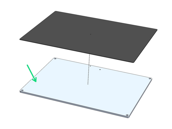
Stick over the aluminium platform plate the magnetic flex-plate sticker.
-
You may find this sticker, being magnetic, stuck onto the back of the black PEI flexplate in the packaging.
-
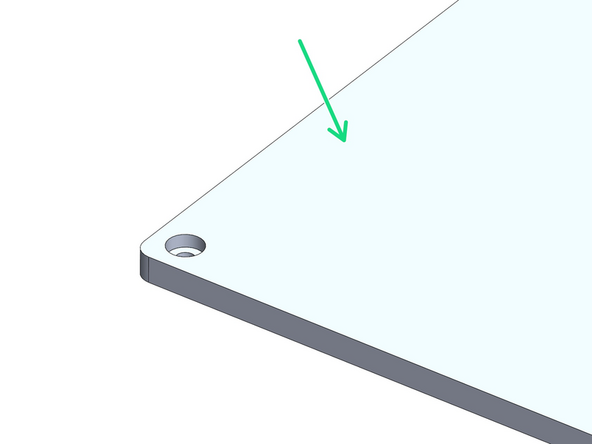
Ensure it is stuck onto the side shown in the images.
-
Peel away the backing paper from the magnetic sheet. Begin by sticking it to one of the shorter edges pressing it down carefully preventing any air bubbles. Use a credit card to press the sticker down, pushing out any potential air pockets.
-
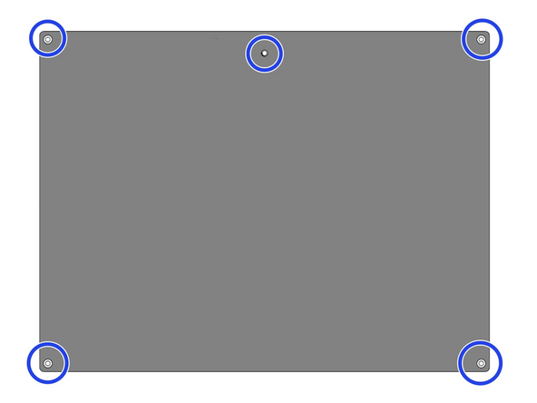
After sticking the sheet down use a craft/box knife to cut away where shown to expose the holes. Use a pin to poke through the other side of the plate to make where you should cut.
-
You don't need to be particularly neat about these cuts, this sticker will have the flexplate go over it.
I put the flex-plate sticker on after the platform was mounted. I did not want mod the flex-plate sticker with holes. I want it to look like my other printers with flex plates. I feel this should be part of the instructions to put it on last or after mounting the bed and no more screws are required for the bed.
You can use an awl from the underside to mark where to make the holes on the top side
Brendan DeBeasi - Resolved on Release Reply
For a neat finish I did this (awl from the underside), then I hand-held an 8mm drill bit and used the hole I'd just made to centre the drill bit. Turned the drill bit gently by hand.
-
-
-
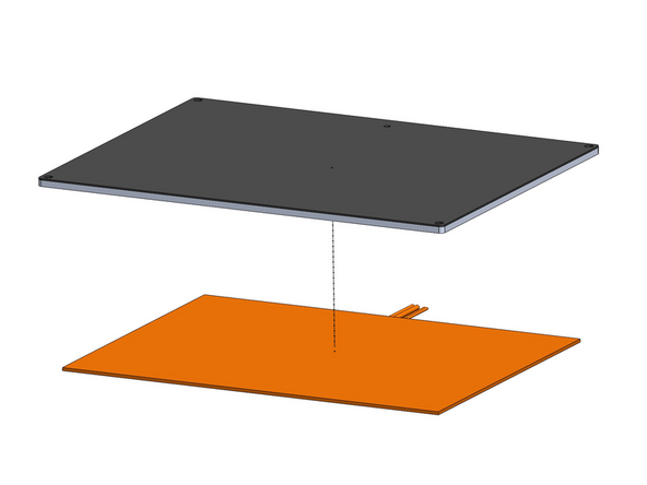
Peel the backing paper away from the heater pad.
-
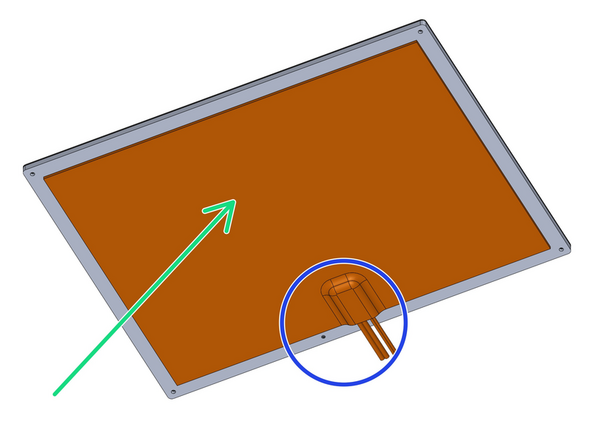
Fix the heater onto the centre of the underside of the platform as shown.
-
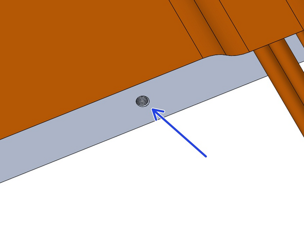
Ensure the cables are on the side with the M4 threaded hole as shown.
-
Make sure the hole is not covered either.
-
-
-
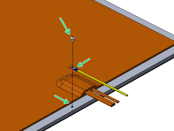
Fix the 1M Earth cable to the platform with an M4 x 6mm button head bolt.
-
-
-
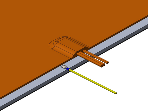
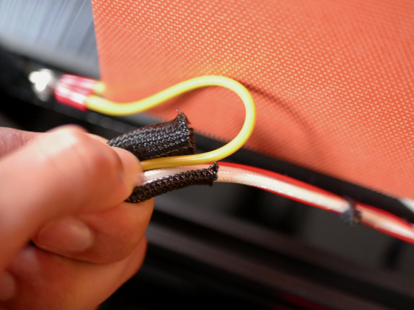
Cut 70cm of the braided sleeving and wrap the heater and earth cables with it.
Later in the assembly, when I need to wrap the wires from the tool changer. I come up short and the wrap isn't long enough to route as shown. It would be helpful here to specify how long the remaining piece should be after this cut.
roger james - Resolved on Release Reply
-
-
-
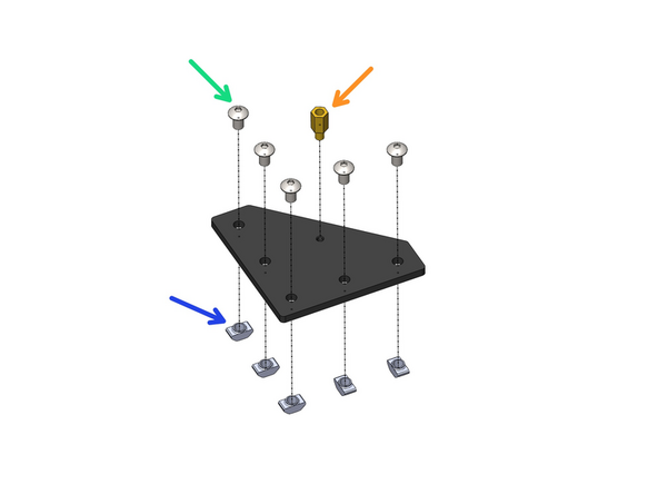
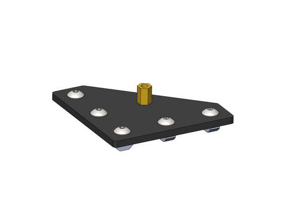
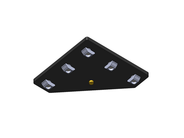
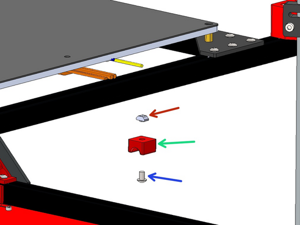
Prepare the four platform brackets as shown.
-
M5 x 8mm Button
-
M5 T-nut
-
M4 x 10mm Brass Standoff
-
-
-
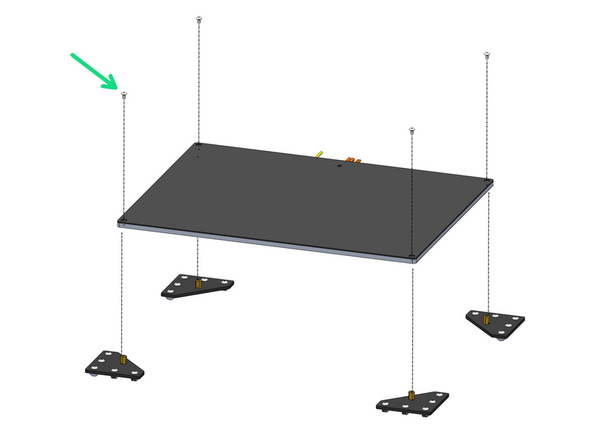
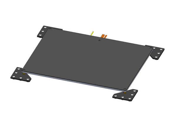
Fix the four brackets onto the platform.
-
M4 x 6mm Button
@brendandebeasi I found the M4 x 6mm to be perfect and the button head to lay below the magnet sticker.
I ended up using m4x6 cap head screws as they lay more flat
Brendan DeBeasi - Resolved on Release Reply
-
-
-
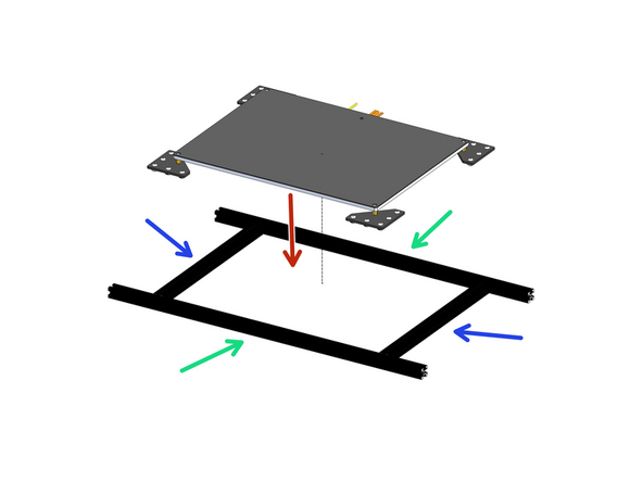
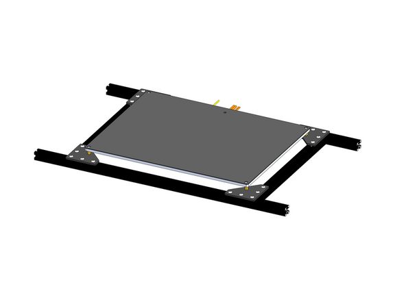
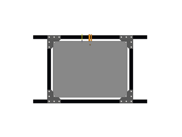
Arrange the extrusions as shown and mount the platform assembly onto them.
-
2020 Extrusion - 630mm
-
2020 Extrusion - 333mm
-
Make sure to push the cables through the centre of the frame.
After tightening everything up, I found it easier to remove the 630mm extrusion and attach it to the Z bracket in step 18. It is much more difficult to handle the platform fully assembled.
David Klingenberg - Resolved on Release Reply
-
-
-
Prepare the Z-brackets
-
M4 x 35mm Bolt
-
M4 T-nut
-
-
-
Mount the platform assembly onto the z-brackets.
-
Align the extrusions flush with the brackets.
Remove the 630mm extrusions from the -platform and attach them individually to the Z brackets. Then, you can align the extrusions flush with the brackets. Finally, drop the rest of the platform onto the 630 mm extrusions and then center it up.
David Klingenberg - Resolved on Release Reply
-
-
-
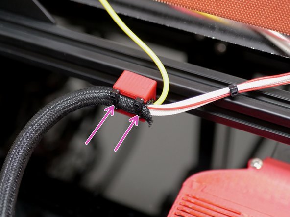
Fix the cables to the bottom of the platform frame with the 3d printed bracket.
-
M5 x 8mm Button
-
M5 T-Nut
-
Use cable ties to secure the heated bed cables to it as shown.
-
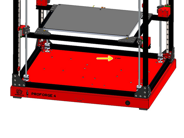
Route the cables into the base.
I think this one should read M5 x 8 Button (as in the illustration)?
-
-
-
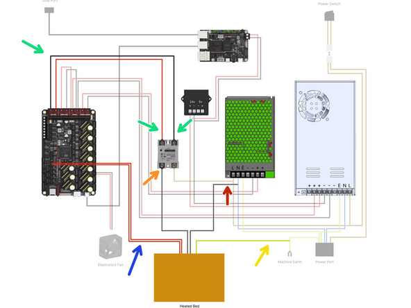
Wire the heated bed as shown:
-
Bed Signal Cables - 30cm
-
Bed Power Cables
-
One cable to SSR Relay
-
One cable to N terminal on 48v PSU
-
Bed Thermistor - Plug into control board
-
Bed Earth - Bolt to Base
Now i have to source a crimping tool and connectors. I'll by the time this is over, I'll definitely have a few tools I never had before.
Brian Mettlen - Resolved on Release Reply
I was a little surprised there were no crimp connectors on the wires for the heater element considering they were you supplied everywhere else. No problem as I have plenty. The thermistor wires seem a little short.
Pete Pubben - Resolved on Release Reply
I was a bit confused by this diagram at first. I thought I would clear up what is going on power-wise. The bed heater takes AC power, so the DC output for the heater bed from the octopus board triggers a relay from the printer board. The relay connects the neutral and line, and energy flows into the heater. The heater pad probably gets hot fast as it's 110v in the USA and 220v in the EU vs. 48v DC out of the board.
David Klingenberg - Resolved on Release Reply
-
Cancel: I did not complete this guide.
18 other people completed this guide.



This should say M5 x 8mm button head not bolt
Jeppy - Resolved on Release Reply
Updated now :)
Makertech 3D -