
-
-
This stage is for the MIC-6 platform upgrade. If you have the default 24V bed please follow this version of stage 5.
-
-
-
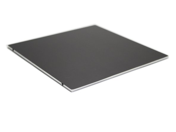
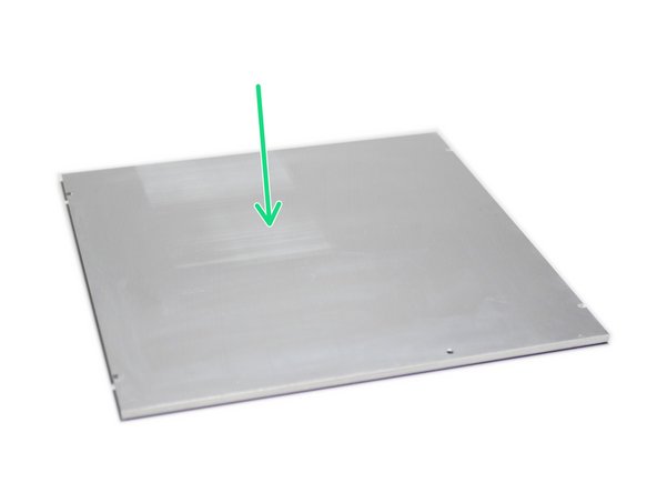
Begin by taking the MIC-6 platform and placing down flat with the machined side up.
-
Clean the surface with an alcohol wipe, making sure it is free of any grease.
-
-
-
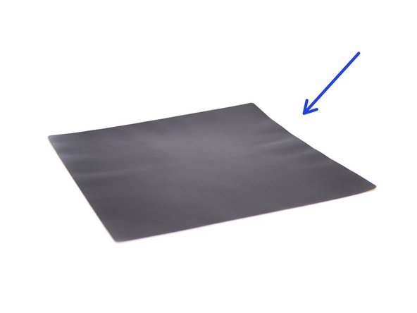
Take the magnetic sheet.
-
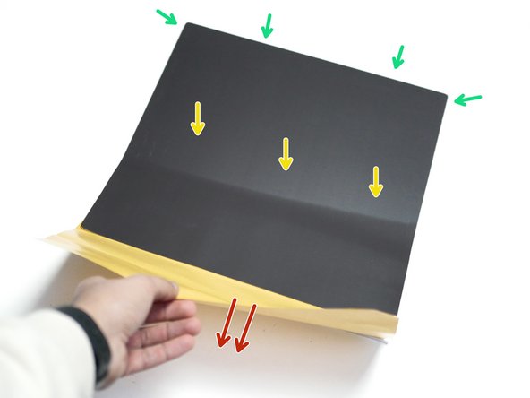
Peel away the backing paper from one edge and align it with an edge on the MIC-6 platform.
-
Carefully pull the backing paper whilst pressing the magnetic sheet down.
-
Take care to avoid air bubbles.
-
-
-
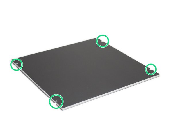
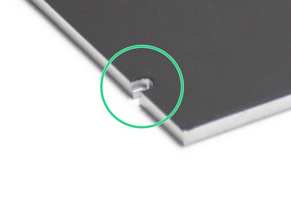
Use a knife to remove the excess magnetic sheet from the platforms mounting slots.
-
-
-
Flip the platform over and wipe down the surface to remove any grease.
-
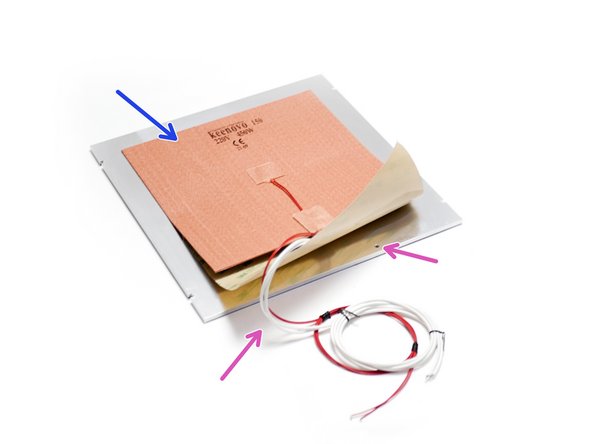
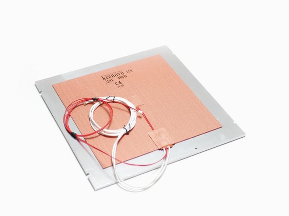
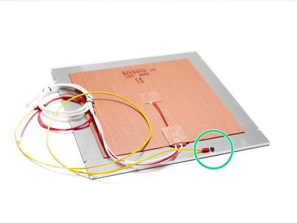
As before with the magnetic sticker, fix the heater pad on in the same way.
-
Before installing the heater, double check it is correctly rated for your mains. In the UK and Europe this should be 220V, in North America this should be 110V. Providing the incorrect voltage to a heater can result in permanent damage.
-
Make sure to orientate the cables so the point to the side that has the M4 threaded hole.
-
Press the heater down firmly.
-
-
-
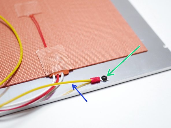
Fix the earth cable to the platform as shown.
-
M4 x 6mm button
-
Ensure that the cable points to the left.
-
-
-
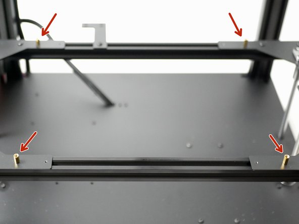
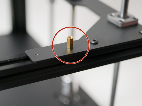
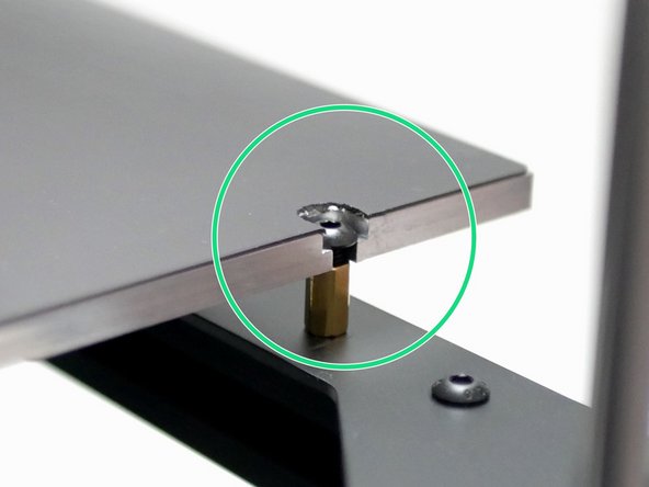
Secure four M4 brass standoffs to the platform brackets as shown.
-
These standoffs can be found in the MIC-6 fastener bag.
-
-
-
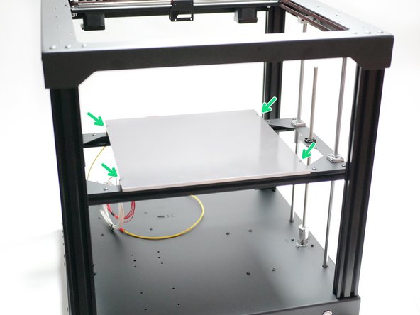
Mount the heated bed to the platform frame.
-
Make sure that the cables point to the rear of the printer.
-
M4 x 6mm Button
Those were in the last step.
-
-
-
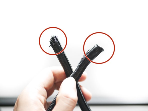
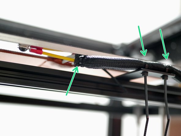
Cut 60CM of the braided sleeving. Use a lighter to melt the ends to prevent fraying.
-
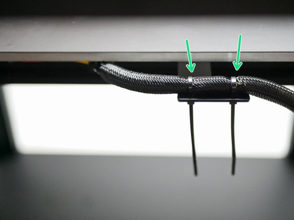
Use cable ties to secure the sleeving to the cable relief bracket.
-
-
-
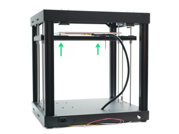
Raise the platform to the top.
-
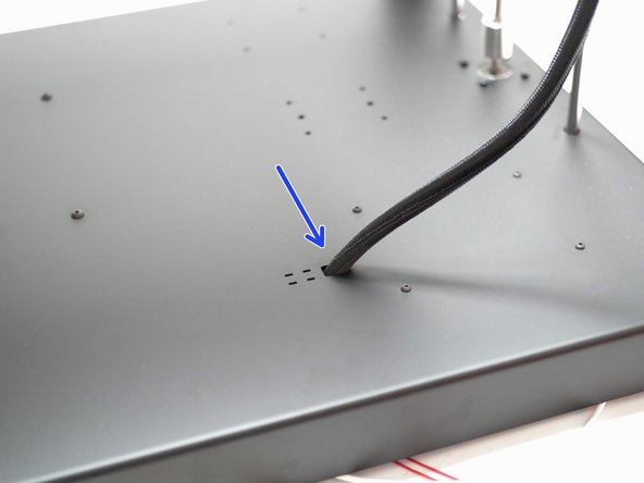
Feed the cables through the hole on the base.
-
Fix the cables to the base with cable ties as shown.
-
-
-
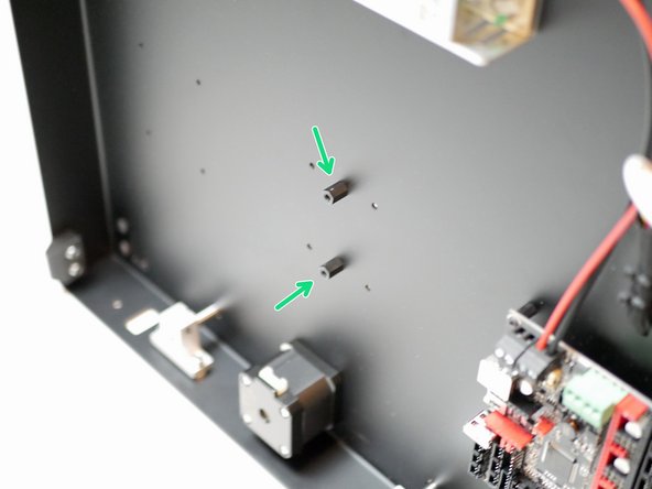
Fix the SSR stand-off's to the base.
-
M4 x 10mm Threaded Spacer
-
Unfortunately, M3 x 10mm threaded spacers were included by mistake in some kits. These can be used instead with M3 x 6mm bolts to mount the SSR.
-
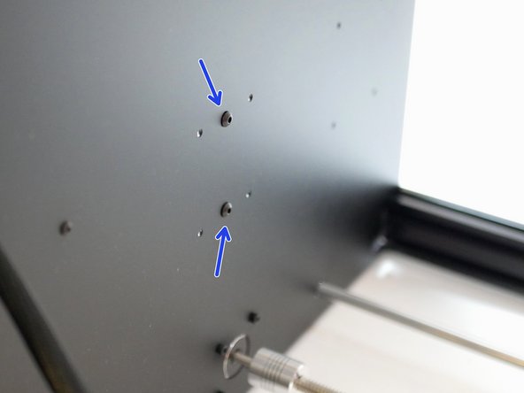
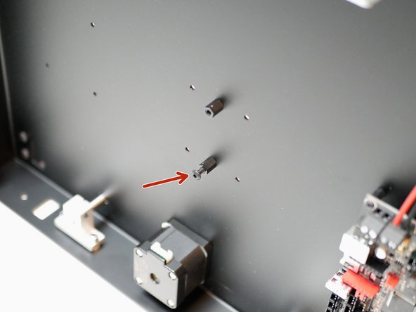
M4 x 6mm Button
-
Loosely fix an additional M4 x 6mm bolt to the lower stand-off
Only M3x10 are available, shall I use them?
Oh so it wasn’t just me searching frantically in vain for an hour for M4 10mm threaded spacer
An SSR needs to have a heatsink of some type. That is why there is an Al plate on the back. Mounting on standoffs will impair it's ability too shed excess temp. It should be mounted directly to the Proforge floor (if the chamber is not heated) or to a independent suspended heatsink/metal (if the chamber is heated).
I think the M4 10mm threaded spacers aren’t in the kit. I’ve only found M3 and M2.5 ones.
same, the ones in the bag with the heater wiring are M3
-
-
-
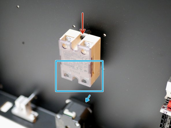
Mount the SSR by first dropping it onto the bolt you loosely fixed in the previous step.
-
Then secure with another M4 x 6mm button head bolt.
-
Tighten both bolts to secure.
-
Double check that terminals 3 and 4 are pointing towards the Z-motor.
Sorry. SSR Just found
I can’t find something look like a SSR. I think it is missing. Will you send me one?
-
-
-
Images to be updated.
-
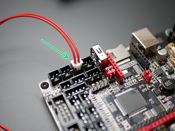
Take the red cable and attach the clamp connector to it.
-
To the other side of the clamp connector attach the cable with XH connector.
-
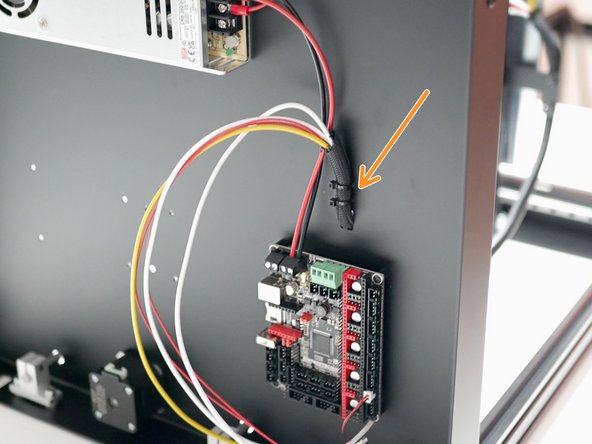
Plug the XH connector into the baord as shown.
For those of us where the 3.5 kit hot end thermistor has only bear wires, an alternate solution is to put a piece of shrink tubing on each of the two ends, then wire together the separate thermistor wires. to the bear wires. Slide the tubing over the connection, heat with a hair dryer and you have a permanent connection. A more elegant solution to the problem.
My kit didn’t have connectors for the thermistor either. I have no idea how to get and crimp one
Shall I use the white connector to connect the 2 red wires with the red and black provided wire with connector ?
Yes, please do.
The big white clamp connector has a screw hole in it for an M3 screw but I couldn’t find a nice place to attach it to.
The kit I received did not include a connector on the thermistor wires. I was able to crimp my own. I’ll update if there are any technical issues later on.
The kit should contain a cable and a white connector to add to the thermistor cable.
-
-
-
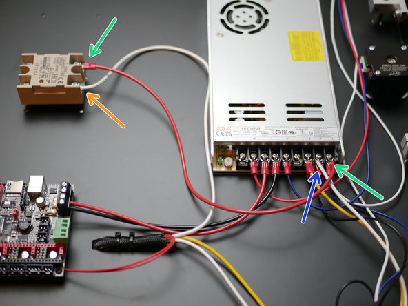
Note, the cover on the SSR can be pulled off to gain better access to the screw terminals.
-
Fix one of the heater cables to the terminal shown on the SSR.
-
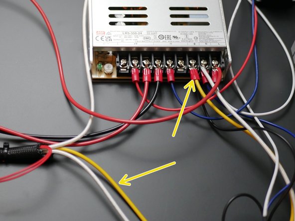
Fix the other heater cable to the Neutral (N) terminal of the power supply.
-
Take a red power cable and connect it from the second terminal on the SSR to the Live (L) terminal on the power supply.
There should be crimped connectors on all of these wires.
really not the electrical setup we would expect from a uk company…
-
-
-
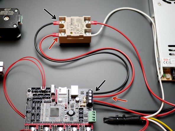
Wire the signal cables from the control board to the other side of the SSR as shown.
-
Red Cable
-
Black cable
-


Cancel: I did not complete this guide.
8 other people completed this guide.

3 Comments
I double-checked my wiring for this step and it all looks correct - yet my bed sensor is reading negative temps.
None of the steps indicate that the threaded risers visible in Step 7 should be installed.
They’re from the previous section I believe.